
Distributed parameter type microstrip circuit
The IF pre-amplifier circuit described utilizes a distributed-parameter microstrip design, which is advantageous for high-frequency applications due to its low loss and compact structure. The operating frequency range of 950 to 1,470 MHz is typical for intermediate frequency (IF) stages in communication systems, allowing for effective signal amplification while minimizing distortion.
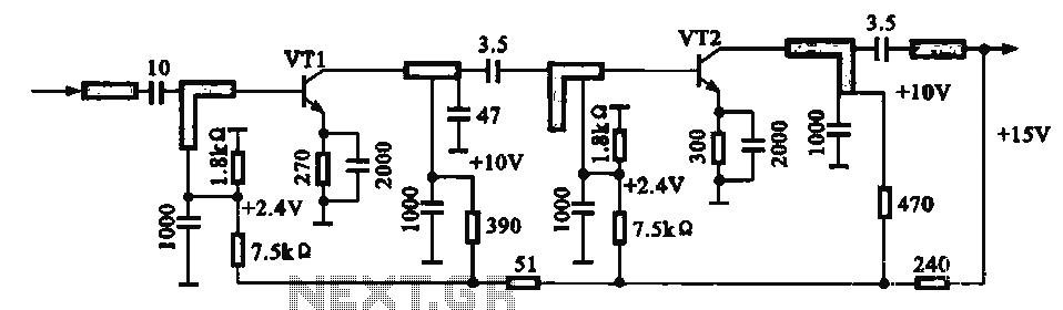
The output impedance of 75 ohms is a standard value in RF applications, facilitating compatibility with other components in the signal chain, such as antennas and mixers. The design incorporates four short high-impedance microstrip lines to connect the power supply to the collector and base of the transistor VT2. This configuration minimizes signal reflection and ensures stable operation at high frequencies.
The base-emitter biasing arrangement is critical for the transistor's operation, ensuring that it remains in the active region for amplification. The self-emitter voltage provides a portion of the necessary bias, while the external voltage source contributes the additional required biasing voltage. This dual-source approach enhances the stability and performance of the amplifier.
The +15V power supply is essential for the proper functioning of the circuit, providing the necessary voltage for transistor operation. The high-impedance isolation inductor connected to the microstrip line serving the IF output prevents unwanted feedback and maintains signal integrity, ensuring that the amplified signal is delivered cleanly to subsequent stages in the signal processing chain.
Overall, the design of this IF pre-amplifier circuit reflects careful consideration of high-frequency performance, impedance matching, and biasing techniques, making it suitable for modern communication systems requiring reliable signal amplification.IF pre-amplifier circuit shown in distributed-parameter type microstrip circuit. It operates in the frequency band 950-1 470 MFk, output impedance of anti-75 Q, the collector and the base of VT2 vri pole power supply is provided through 4 short high impedance microstrip line: transistor base-emitter bias press consists of two parts: one is self-emitter voltage of the transistor, the other part is fed from an external voltage pole group. +15 V power supply is made by the high impedance IF output cable isolation inductor microstrip line fed.
Related Circuits

When utilizing a regulated power supply to decrease voltage, there exists a risk of component failure within the supply, potentially resulting in damage to connected equipment. While a fuse can provide protection against excessive current draw, it may not...
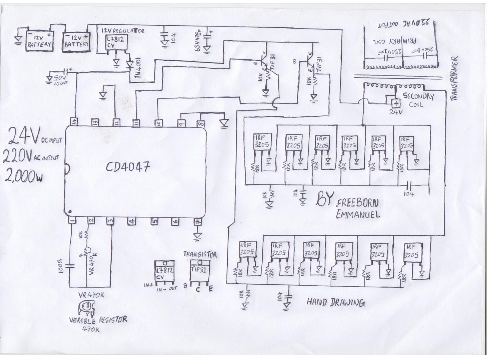
The diagram illustrates a modified square wave inverter circuit. By adjusting the frequency resistor (VR 470k), the inverter's output frequency can be optimized to effectively power a freezer compressor and various other electronic appliances in a living room. The...

This FM transmitter circuit is very simple and has acceptable transmission. The signal transmitted from this FM transmitter circuit can be received at almost 300 meters in open air. The circuit requires a 3-volt operating voltage and can be...

This document outlines a straightforward circuit diagram for a musical horn utilizing two NE555 integrated circuits (ICs). Both ICs are configured as astable multivibrators. The output from the first multivibrator is connected to the discharge pin (pin 7) of...
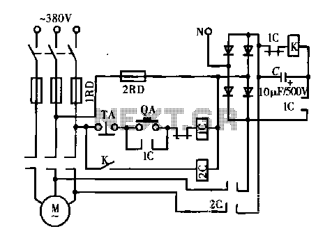
A DC motor is depicted in a dynamic braking circuit. When the stop button (SB2) is pressed, the contactor (KM1) is deactivated, causing its movable contact to disconnect, which interrupts the electrical voltage. Additionally, relay (KV) is activated, closing...
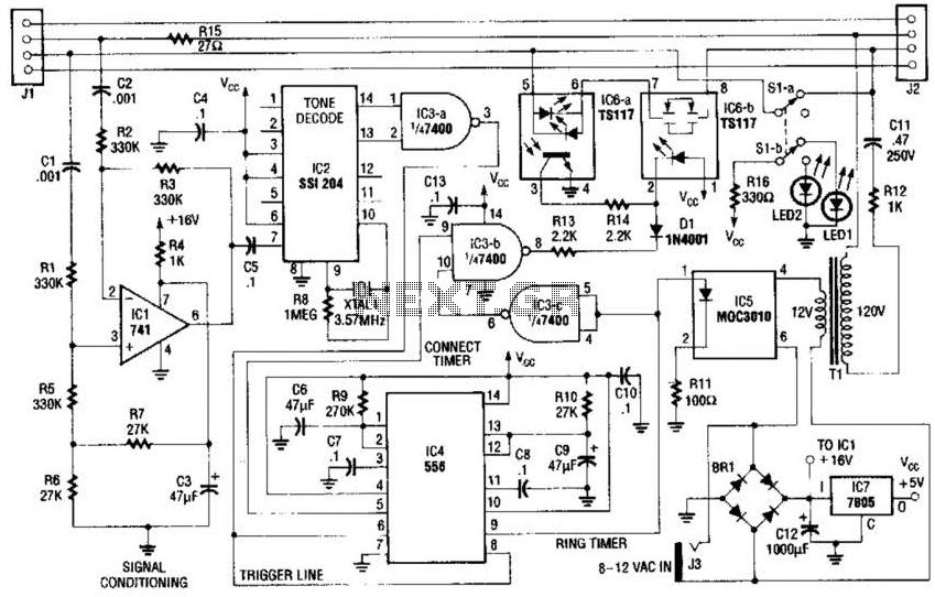
The fax mate separates the fax machine from the phone line, rings the fax machine on command, connects equipment to incoming lines, and senses the end of the message. When a touch tone pound signal (#) is detected, it...