
TWO SLEW RATES

Peltier-effect semiconductor thermoelements maintain uniform cooling temperatures necessary for accurate specific gravity measurements. A null-position detecting circuit employs a differential transformer to sense the position of the movable core at the end of the float.
A simple circuit utilizes the Motorola MBS-4991 silicon bilateral switch to provide phase control of a triac. A 1-megohm potentiometer varies the conduction angle of the triac from 0° to about 170°, achieving better than 97% of full power to the load at maximum setting. The conduction angle remains consistent for both half-cycles at any given potentiometer setting.
When controlling a nonlinear device, such as an incandescent lamp, fine resolution at the high end is desirable, as a small change in current can cause a significant change in brightness. At the low end, coarser resolution suffices. The circuit described allows for desired compression using a multiplying Digital-to-Analog Converter (DAC). A negative 10-V reference is fed through resistor R1 to an inverting amplifier (A1), which has an initial gain set to unity by R2. The output of A1 provides a positive variable reference to the DAC. The DAC output feeds back through resistor R3, reducing the amplifier's gain as the DAC data increases. This feedback results in a gradually reduced variable reference, making each step progressively smaller. With the specified values, as the DAC data approaches full scale, the reference approaches one-fourth of its original value, yielding an output with four times the resolution at the high end compared to the low end. By decreasing R3's value, greater compression and higher resolution can be achieved. The variable reference output may also be beneficial in certain applications.
A simple rectifier circuit can replace the battery in a vacuum-tube voltmeter (VTVM), providing good regulation and eliminating the need for frequent battery replacement. It is essential to remove the battery before using the supply. The AC source can be the 6.3-V secondary of a filament transformer or the terminals of a 6.3-V pilot lamp in any AC equipment.
The discharge-type single trigger timing circuit formed by a Programmable Unijunction Transistor (PUT) operates as follows: when there is no input signal, PUT1 and transistor VT1 are cut off, and capacitor C1 charges to the power supply voltage (Ucc). When an input signal is applied, PUT1 and VT1 conduct, allowing current to flow through the load (RL).The decimal value of the eight input lines is displayed on three seven-segment displays. Although chips exist to perform this function for single displays, none include the possibility of displaying numbers greater than 9. No EPROM is necessary in this design. It operates by using two synchronized counters, one that generates an 8-bit binary outpu t, and a second that drives the display. If the display is updated only when the binary counter is at the same value as the input, then the display will show the decimal value of the input. IC4 is the binary counter, and IC6 to IC8 form the display/counter section. IC5a and IC5b form the astable, which clocks both counters at 5 kHz. The minimum display refresh rate is, therefore, 20 times per second, IC1 and IC2 are two 4-bit comparators, ganged to form an 8-bit comparator.
This compares the output of the binary counter (IC4) with the binary input taken from the circuit under test. Resistors RI to R8 pull down the input lines to prevent them from floating when no input is connected.
When the comparator inputs are equal, pin 6 of IC2 goes high, triggering the monostable (IC3ab), which outputs a brief pulse. This latches the value of the display counters (IC6 to IC8) to the display. When IC4 reaches avalue of 256, the link between pins 11 and 12 resets the chip, and this resets the display counter also.
(View) Peltier-effect semi-conductor thermoelements maintain uniform cooling temperatures required for accurate specific gravity measurements. Null-position detecting circuit uses differential transformer to sense position of movable core at end of float.
-C. W. Hargens, Semiconductors Cool and Control Density Gage, Electtonics, 31:49, p 80-8l. (View) Simple circuit uses Motorola MBS-4991 silicon bilateral switch to provide phase control of triac. 1-megohm pot varies conduction angle of triacfrom0o to about 170o, to give better than 97% of full power to load at maximum setting.
Conduction angle is the same for both half-cycles at any given setting of pot. - Circuit Applications for the Triac, Motorola, Phoenix, AZ, 1971, AN-466 p 5. (View) When controlling a nonlinear device, such as an incandescent lamp, it is desirable to have fine resolution at the high end, where a small change in current can cause a large change in brightness. At the low end, coarser resolution is quite adequate. Using the circuit shown, any desired compression can be produced using just about any multiplying DAC.
A negative 10-V reference is fed through R1 to inverting amplifier A1, which has an initial gain set to unity by R2. A1`s output supplies a positive variable reference to the DAC. The DAC output provides additional feedback through R3, reducing the amplifier`s gain as the DAC data increase.
The variable reference is gradually reduced so that each step is progressively smaller than the one before. With the values shown, as the DAC data approaches full-scale; the reference approaches 1/4 of its original value.
This produces output with four times as much resolution at the high end as at the low end. By decreasing the value of R3, greater compression and higher resolution can be achieved. The variable-reference output also can be useful in some applications. (View) Simple rectifier circuit replaces battery in vacuum-tube voltmeter. Provides good regulation and eliminates need for frequent battery replacement. Remove battery before using supply. AC source can be 6. 3-V secondary of filament transformer or terminals of 6. 3-V pilot lamp in any AC equipment. -P. Alexander, Battery Replacement Circuit for VTVM, QST, Jan. 1976, p 42-43. (View) Figure 1 is the discharge type single trigger timing circuit formed by PUT. When there is no input signal, PUT1 cuts off, and so does the transistor VT1. At this time, C1 charges to the power supply voltage Ucc. If we add the input signal, PUT1 and VT1 conduct, current flows through the load RL. At the same time 🔗 External reference
Related Circuits
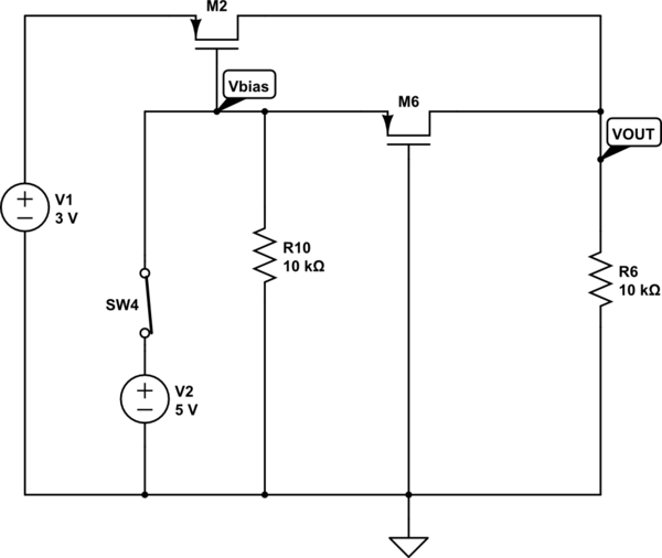
The output voltage (VOUT) is intended to be 3V when the switch is open and 5V when the switch is closed. The simulation correctly reflects the desired outcome when the switch is open; however, it does not perform as...
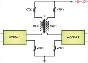
Connecting two PCs via modems using a twisted pair cable may not yield any results because the modems are designed to operate over a phone line. The scenario described involves the attempt to establish a connection between two personal computers...

This is a two-station intercom system that operates using a pair of wires connecting each intercom unit. Each unit is self-contained, featuring its own battery, speaker, microphone, and amplifier circuit. An LM386 audio power amplifier is utilized in the...

The DC motor E inversion control circuit utilizes a loop configuration with various relay contacts. It employs a single set of normally open/normally closed relay contacts. When both inputs A and B are low, relay KI is activated. In...
The water resource is being transformed into a valuable and rare commodity. Consequently, promoting water-saving irrigation has become a priority for countries worldwide to address the water resource crisis and achieve agricultural modernization. This text proposes a cipher scheme...
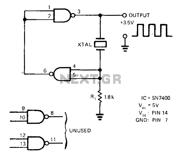
A SN7400 quartz crystal and a resistor provide a square-wave output of approximately 3.5 V. The circuit operates reliably at frequencies from 120 kHz to 4 MHz. The circuit utilizes a SN7400 integrated circuit, which is a quad two-input NAND...