
simple fm transmitter
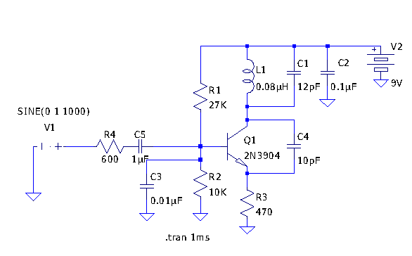
The FM transmitter circuit typically consists of a few key components: an oscillator, a modulator, an amplifier, and an antenna. The oscillator generates a radio frequency signal, which is then modulated with the audio signal that is to be transmitted. The modulation process alters the frequency of the carrier wave in accordance with the audio input, allowing the sound to be transmitted over the airwaves.
The circuit may include a transistor or an integrated circuit (IC) as the main active component. A common choice for the oscillator is the Colpitts oscillator configuration, which provides stable frequency generation. The modulation can be achieved using a capacitor coupling method, where the audio signal is fed into the base of the transistor, affecting the oscillation frequency.
In terms of components, a few resistors and capacitors are required to set the operating frequency and stabilize the circuit. The choice of the antenna is also critical, as a well-designed antenna can significantly enhance the transmission range. A simple dipole or monopole antenna can be used, depending on the desired range and frequency.
Power supply considerations must also be addressed, as the circuit requires a stable voltage to function effectively. A battery or a regulated power supply can be employed, ensuring that the transmitter operates without fluctuations that could affect performance.
Overall, this simple FM transmitter circuit is an excellent project for those interested in learning about radio frequency transmission and modulation techniques, providing a practical application of electronic principles.Schematic and description to make fm transmitter. It is a simple fm transmitter circuit with minimum components but it has a long range. .. 🔗 External reference
Related Circuits
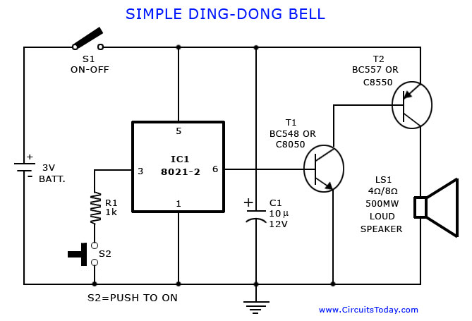
A tone generator circuit, which can be used to create a simple calling bell circuit, is illustrated here. It is constructed using the 8021 integrated circuit (IC), which includes built-in circuitry for producing a "ding-dong" sound. The tone generator circuit...
The scope of the AM transmitter is designed to handle amplitude modulated (AM) double sideband (DSB) signals. A standard AM signal consists of a carrier wave and two symmetrically spaced sidebands. The two sidebands carry the same amplitude and...
Tetsuo Kogawa's circuit is well documented, although not in a conventional schematic form. It has been entered into LTSpice for analysis, and the schematic is presented online with some comments. The circuit includes a small air variable capacitor (C1)...
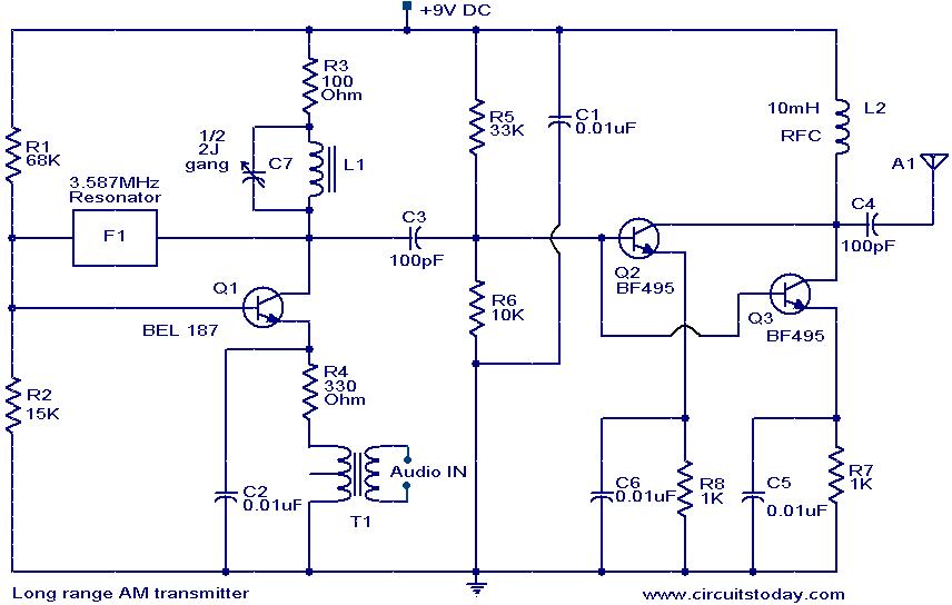
The circuit diagram of an AM transmitter circuit based on three transistors. With correct tuning and a matching antenna, the transmitter can effectively transmit amplitude-modulated signals. The AM transmitter circuit utilizes three transistors configured to amplify and modulate the input...
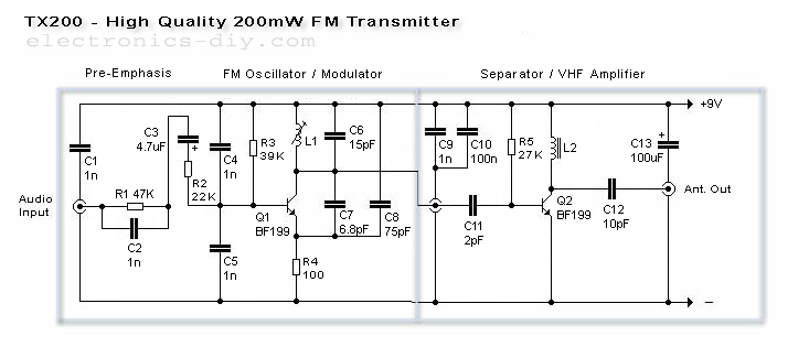
The TX200 is an advanced and significantly larger VFO/VCO FM transmitter, recognized as one of the best transmitters available. It is a 200mW FM transmitter designed for stereo PLL applications, providing a wide range for broadcasting music throughout a...
The two circuits di atas illustrate opening a relay contact a short time after the ignition or light switch is turned off. The capacitor is charged and the relay is closed when the voltage at the diode anode rises...