
Two-Transistor Sine-Wave Oscillator

The described oscillator circuit is designed to generate stable sine wave signals using a two-transistor configuration. The fundamental mode operation of the crystal ensures that the oscillator is tuned to the desired frequency with high precision. The choice of capacitors CT and C2 is critical for frequency selection and stability; their values must be adjusted according to the target frequency as outlined.
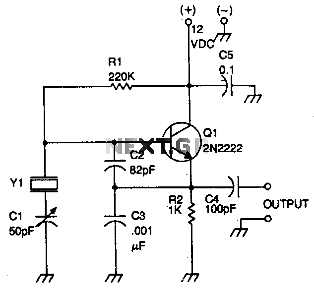
For a frequency of 1 MHz, a capacitance of 2,700 pF is recommended, which helps to set the oscillation frequency by creating a resonant circuit with the crystal. At 5 MHz, the capacitance should be reduced to 680 pF, and for 10 MHz, 330 pF is appropriate. For applications requiring frequencies up to 20 MHz, a minimum capacitance of 150 pF is suggested. This systematic adjustment of the capacitors allows for fine-tuning of the oscillator frequency and ensures optimal performance.
The output of the oscillator is characterized by a near-perfect sine wave, making it suitable for various applications where signal purity is essential, such as in audio or RF applications. The output voltage range of 2 to 6 Vpp indicates that the circuit can provide sufficient signal level for driving subsequent stages in a circuit.
To achieve the best waveform quality, it is advisable to experiment with the values of capacitors Ci and C2. By carefully varying these capacitances, one can minimize distortion and improve the overall signal integrity. This adaptability is crucial in practical applications where different load conditions or circuit configurations may affect the oscillator's performance.
In summary, this oscillator circuit provides a versatile solution for generating sine wave signals across a range of frequencies, with specific attention to component values that dictate its operational characteristics. The careful selection of capacitors and the ability to adjust them for optimal performance are key aspects of this design. This oscillator uses two transistors and operates the crystal in the fundamental mode. CT and C2 should be about 2 700 pF for 1 MHz, 680 pF for 5 MHz, and 330 pF for 10 MHz. 150 pF can be used for up to 20 MHz. The output is a near perfect sine wave. Try varying Ci and C2 for best waveform. About 2 to 6 Vpp is available.
Related Circuits
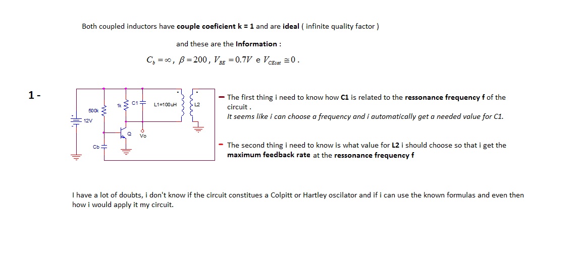
The first thing to understand is how capacitor C1 is related to the resonance frequency f of the circuit. It appears that selecting a frequency allows for the automatic determination of the necessary value for C1. There are uncertainties...
The circuit produces a clean sine wave signal suitable for audio testing or other applications requiring a high-quality sine voltage source. It utilizes a widely available dual operational amplifier, the Texas Instruments TL072CP. The component values yield an output...
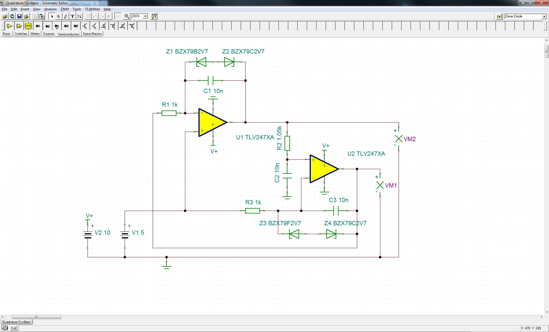
The circuit is close to sustaining oscillation. Changing resistor R2 to 10.5k will enable it to sustain oscillation. The original authors of the referenced note are no longer available for consultation. Oscillators of this type can be complex, as...
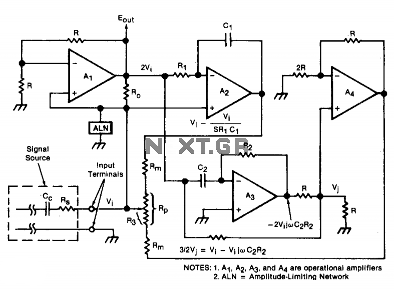
An oscillator/amplifier is resistively tunable over a wide frequency range. Feedback circuits containing operational amplifiers, resistors, and capacitors synthesize the electrical effects of inductance and capacitance in parallel between the input terminals. The synthetic inductance and capacitance, and therefore...
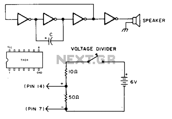
This simple circuit utilizes the 7404 low-power Schottky hex inverter. Capacitor C is a 5 to 30 µF electrolytic capacitor selected for the desired pitch. The speaker is a 2-inch, 8-ohm unit. The circuit employs a 7404 low-power Schottky hex...
This circuit operates with fundamental-mode crystals in the frequency range of 1 MHz to 20 MHz. Feedback is regulated by the capacitor voltage divider formed by capacitors C2 and C3. The RF voltage across the emitter resistor supplies the...