
Wide frequency oscillator
The described oscillator/amplifier circuit employs a configuration that enables the adjustment of its resonant frequency through resistive tuning. This is achieved using a feedback network that integrates operational amplifiers, resistors, and capacitors to mimic the behavior of inductors and capacitors, effectively creating a synthetic LC circuit.
In this setup, the operational amplifiers A1 and A2 serve as the core active elements, amplifying the input signal while maintaining stability across the desired frequency range. The feedback loops are critical for determining the gain and frequency response of the circuit, allowing for fine-tuning of the output characteristics.
The potentiometer plays a vital role in this configuration, as it allows for the adjustment of the synthetic inductance and capacitance by varying its resistance. This adjustment alters the resonant frequency, which is the frequency at which the circuit exhibits maximum response. The input signal is connected to the noninverting terminals of A1 and A2, ensuring that the amplification process is responsive to changes in the input voltage.
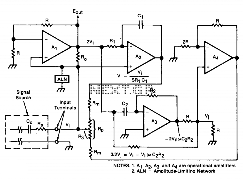
The feedback network's output voltages, which are a function of the input voltage V, can be monitored at various nodes throughout the circuit. These voltages provide insight into the circuit's performance and can be used for further analysis or modifications. This design offers versatility and precision in applications requiring a tunable oscillator or amplifier, making it suitable for a wide range of electronic applications.An oscillator/amplifier is resistively tunable over a wide frequency range. Feedback circuits containing operational amplifiers, resistors, and capacitors synthesize the electrical effects of an inductance and capacitance in parallel between the input terminals. The synthetic inductance and capacitance, and, therefore, the resonant frequency of the input admittance, are adjusted by changing a potentiometer setting.
The input signal is introduced in parallel to the noninverting input terminals of operational amplifiers Aj and A2 and to the potentiometer cursor. The voltages produced by the feedback circuits in response to input voltage V^ are indicated at the various circuit nodes.
🔗 External reference
Related Circuits
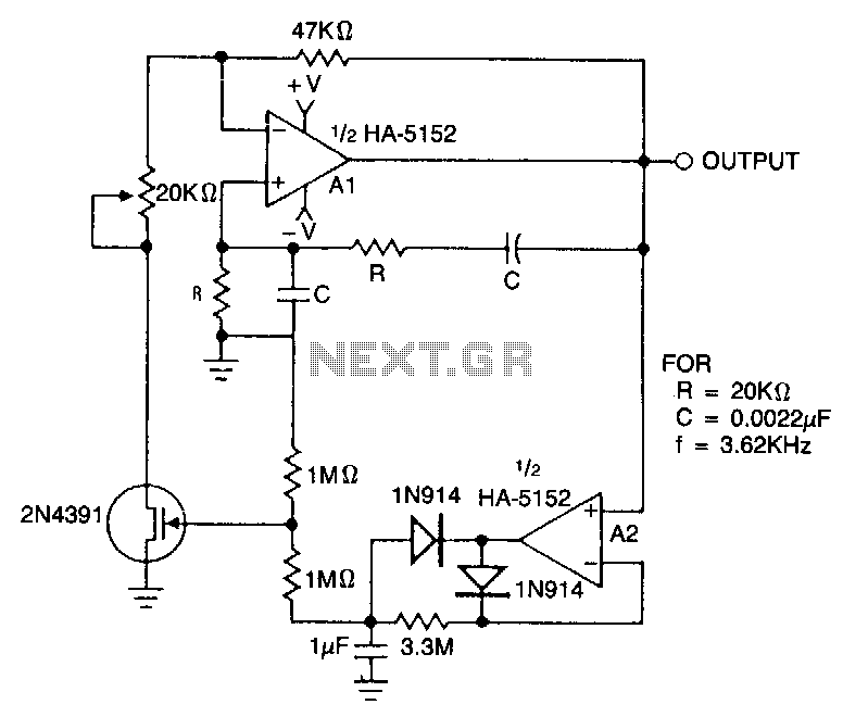
This circuit employs an HA-5152 dual operational amplifier and a field-effect transistor (FET) to create a low-voltage, low-power Wien bridge sine-wave oscillator. The frequency of oscillation is controlled by resistors and capacitors, while the FET functions as a voltage-controlled...
Unlike conventional small-signal methods, employing large-signal, time-domain design techniques facilitates the development of low-noise grounded-base oscillators suitable for VHF/UHF applications. The implementation of large-signal, time-domain design techniques in the creation of grounded-base oscillators represents a significant advancement in the field...
Programming of the PIC microcontroller is required prior to its utilization in this circuit, which necessitates the use of a programmer. A suitable programmer can be located by searching for "Multi-PIC Programmer." The PIC microcontroller serves as the core component...
The DC path is established from the negative side (ground) of VCC through RE, Q1, T1, and returns to the positive side of VCC. The figure clearly illustrates that both the AC and DC components flow through the tank...
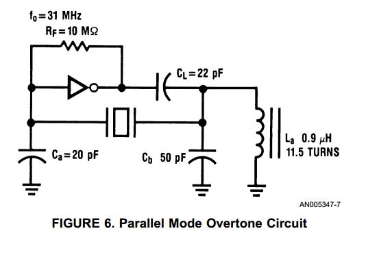
With the advent of high speed HCMOS circuits, it is possible to build systems with clock rates of greater than 30 MHz. The familiar gate oscillator circuits used at low frequencies work well at higher frequencies and either LC...
This 1 kHz linear-scale analog frequency meter circuit utilizes the 555 timer as a pulse counter. The frequency is displayed on meter M1, a 1 mA meter, which can be calibrated to indicate readings from 0 to 1 kHz. The...