
Ultra wideband RF detector design challenge
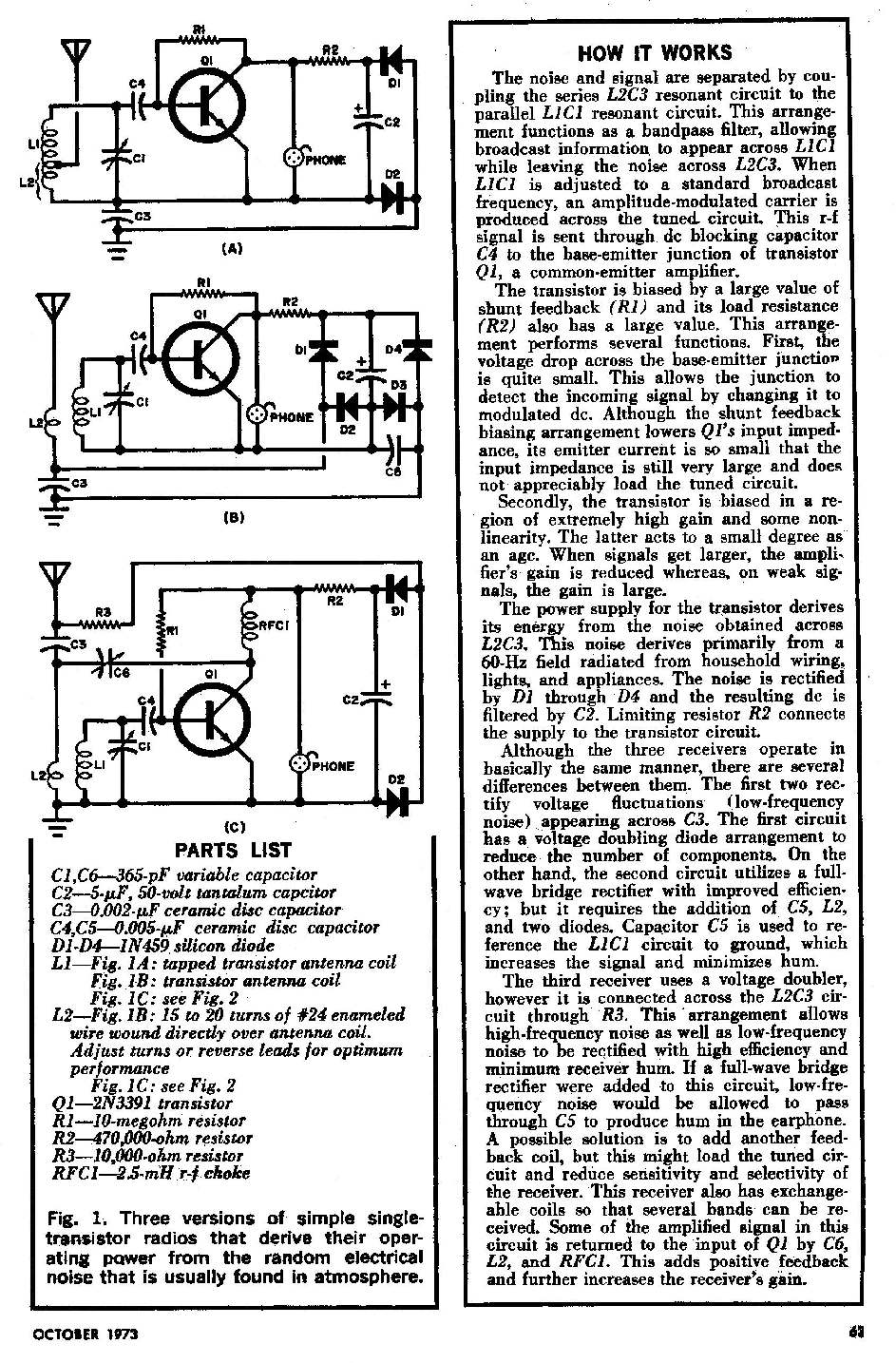
The design of a wideband RF detector incorporating multiple resonant LC tanks offers the capability to capture a broad spectrum of radio frequencies. The LC tank circuits serve as selective filters that resonate at specific frequencies, allowing the detector to identify and process signals within the designated frequency ranges.
The proposed configuration suggests employing a series of LC tank circuits, each tuned to different frequencies spaced 5 to 10 MHz apart. This spacing is crucial for ensuring that the detector can effectively cover a wide frequency range while maintaining sensitivity to the desired signals. The exception of 1 MHz spacing from 9 MHz indicates a focus on finer resolution in that specific frequency band, which may be relevant for applications requiring precise detection in that range.
Each LC tank circuit consists of an inductor (L) and a capacitor (C) arranged to form a resonant circuit. The resonant frequency (f) of each tank is determined by the formula:
f = 1 / (2π√(LC))
Where L is the inductance in henries and C is the capacitance in farads. By selecting appropriate values for L and C, the desired resonant frequencies can be achieved.
The output from each LC tank can be fed into a common detection stage, which may include a diode for envelope detection or a more complex demodulation circuit, depending on the intended application. The output signals can then be processed further for amplitude measurement or converted to a digital format for display or analysis.
In summary, the design of a wideband RF detector using resonant LC tanks provides a versatile solution for RF signal detection across a broad frequency range, with specific tuning to enhance performance in critical areas of interest. Proper component selection and circuit design will ensure optimal functionality and sensitivity of the detector.I`d like to make a wideband RF detector. I`m thinking of using a range of resonant LC tanks, 5 to 10 mhz apart, (except / or 1 mhz apart from 9 to.. 🔗 External reference
Related Circuits
A circuit designed to detect the interruption of a light beam. The initial circuit was a light/dark detector using a photoresistor, which, while capable of detecting light interruptions, suffered from significant interference due to ambient light. This led to...
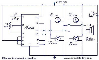
The circuit diagram of an ultrasonic mosquito repeller is presented. This circuit operates on the principle that sound frequencies in the ultrasonic range, above 20 kHz, can repel insects such as mosquitoes. It utilizes a Phase-Locked Loop (PLL) integrated...
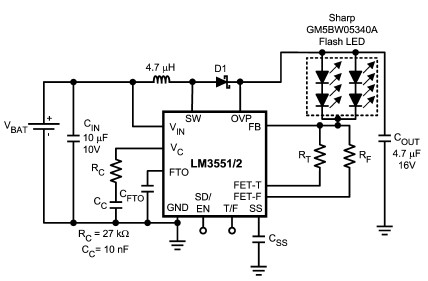
The LM3551 and LM3552 are fixed frequency, current mode step-up DC-DC converters featuring two integrated NFETs. These devices facilitate the design of a straightforward and highly precise LED brightness control system. They are capable of driving loads up to...
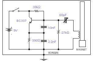
This basic oscillator will detect the Earth magnetic field. The ferrite rod and coil are taken from an old Medium Wave receiver and a small magnet is glued at one end. Tune to a medium wave commercial station until...
This circuit utilizes a complementary pair consisting of an npn metallic transistor T1 (BC109) and a pnp germanium transistor T2 (AC188) to detect heat. The circuit is designed to leverage the thermal sensitivity of the complementary transistor pair, where the...
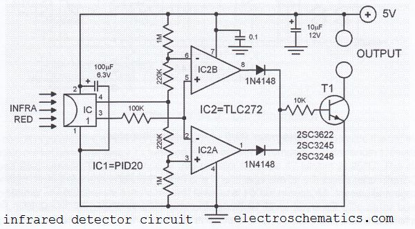
This infrared detector circuit utilizes a passive infrared detector component, PID20, which converts heat radiation into electrical impulses. The output voltage of the PID20 increases when an object approaches, provided that the object is warmer than the surrounding environment....