
ultrasonic mosquito repeller
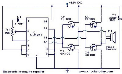
The ultrasonic mosquito repeller circuit leverages the characteristics of sound waves to deter mosquitoes effectively. The core component, the CMOS 4047 PLL IC, is versatile and well-suited for generating stable frequencies. In this application, it is configured in astable mode to produce a continuous square wave output at 22 kHz, which falls within the ultrasonic frequency range.
The output from the CMOS 4047 is relatively low in amplitude, necessitating amplification to ensure that the sound waves can effectively propagate through the environment. The complementary symmetry amplifier, which consists of four transistors arranged in a push-pull configuration, is employed to amplify the signal. This arrangement allows for efficient power usage and improved linearity in the amplification process, ensuring that the output maintains the integrity of the original signal while increasing its amplitude.
Following amplification, the signal is fed into a piezoelectric buzzer. The piezo buzzer is specifically designed to convert electrical energy into mechanical vibrations, producing sound waves. In this application, the buzzer is capable of generating ultrasonic frequencies that are inaudible to humans but can be perceived by mosquitoes. This targeted approach exploits the sensitivity of mosquitoes to specific sound frequencies, which can disrupt their mating behaviors and feeding patterns, effectively reducing their presence in the vicinity.
In summary, the ultrasonic mosquito repeller circuit is an effective solution for insect deterrence, utilizing a combination of a PLL oscillator, a complementary symmetry amplifier, and a piezo buzzer to generate ultrasonic frequencies that repel mosquitoes. The design emphasizes efficiency and functionality, making it a practical choice for pest control applications.Here is the circuit diagram of an ultrasonic mosquito repeller. The circuit is based on the theory that insects like mosquito can be repelled by using sound frequencies in the ultrasonic (above 20KHz) range. The circuit is nothing but a PLL IC CMOS 4047 wired as an oscillator working at 22KHz. A complementary symmetry amplifier consisting of four tra nsistor is used to amplify the sound. The piezo buzzer converts the output of amplifier to ultrasonic sound that can be heard by the insects. 🔗 External reference
Related Circuits
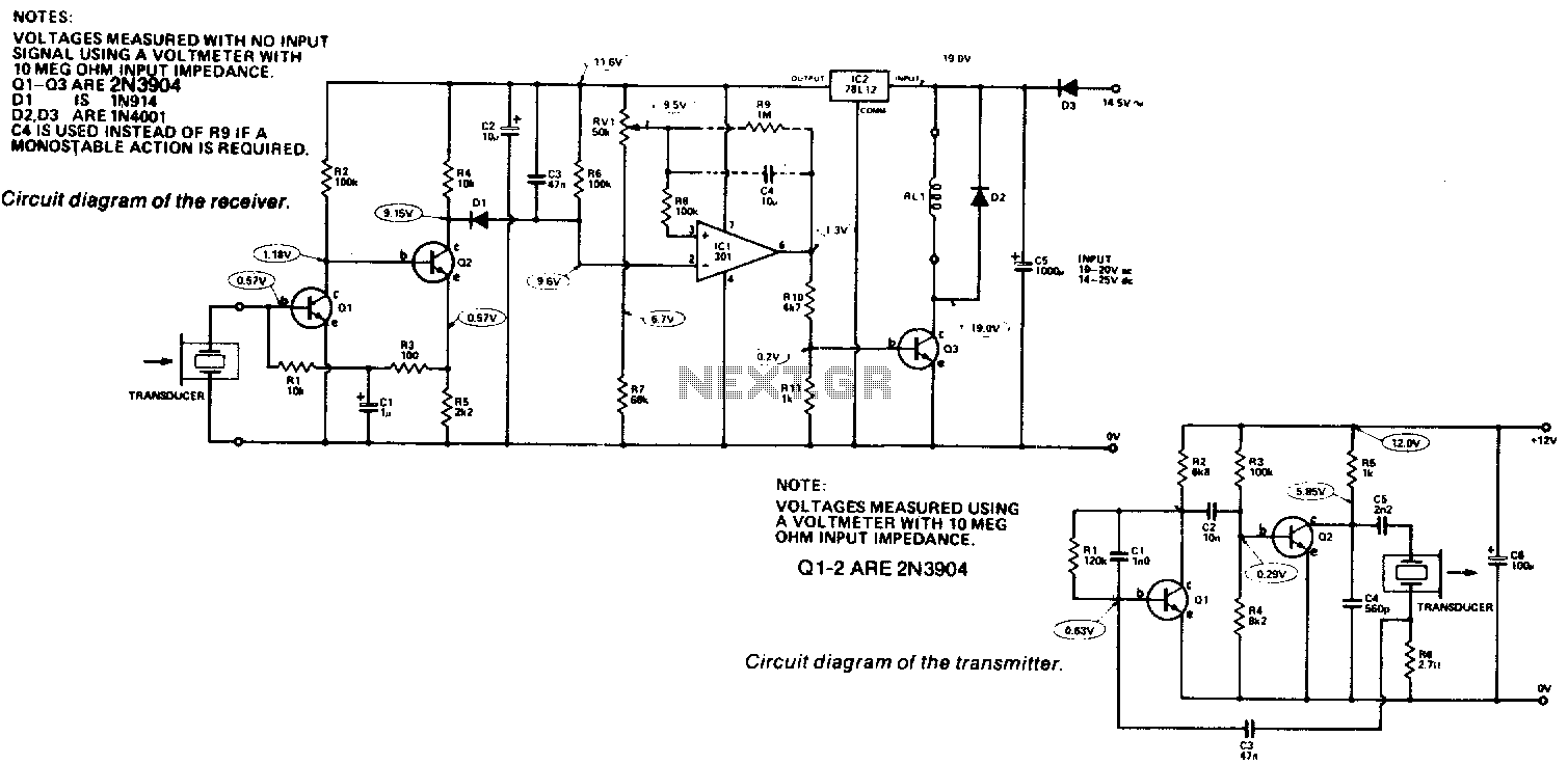
Receiver. The output from the transducer is amplified by Q1 and Q2, and rectified by D1. The voltage on pin 2 of IC1 will become more negative as the input signal increases. IC1 is utilized as a comparator, comparing...
The ultrasonic sensor circuit comprises a transmitter and a receiver, which are essential for remote control applications. The circuit operates at sound frequencies above 20 kHz, typically between 40 kHz and 50 kHz, powered by a 9V battery. When...

Nowadays, almost every house is equipped with an outdoor lamp that features a motion sensor. This device eliminates the need to navigate in the dark when approaching the front door. Outdoor lamps with motion sensors enhance safety and convenience by...
The following circuit illustrates the connection of the Devantech SRF04 Ultrasonic Sensor to the SV203 powered PPRK Circuit Diagram. This circuit is based on the Devantech SRF04 sensor and features a minimum initiation time of 10 milliseconds for the...
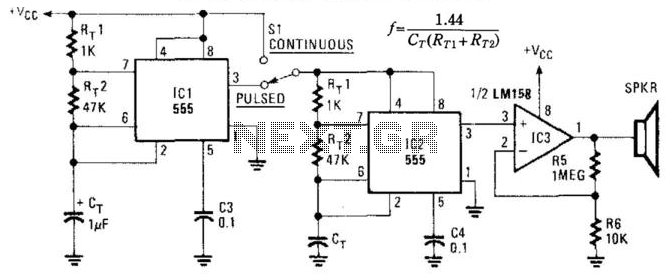
This circuit utilizes two NE555 timer IC devices to generate either pulsed or continuous ultrasonic signals. The values of CT for both pulse rate and ultrasonic frequencies can be calculated accordingly. SPKR refers to a small hi-fi tweeter. The circuit...
The mobile robot is designed to operate in unknown and uncertain environments, featuring autopilot capabilities while avoiding obstacles. It utilizes ultrasonic sensors for range finding due to their simplicity, speed, and cost-effectiveness in information processing. These sensors facilitate functions...