
Ultrasonic switch
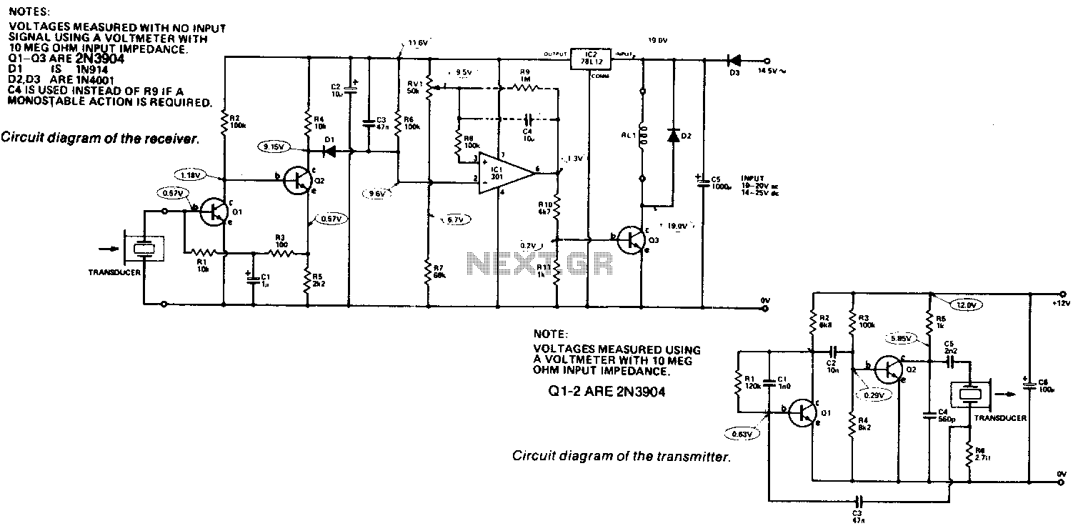
The described circuit functions as a sound level receiver, integrating amplification, rectification, and oscillation detection. The transducer captures sound waves and converts them into an electrical signal, which is initially processed by two transistors, Q1 and Q2, configured as a non-inverting amplifier. This configuration enhances the input signal's amplitude, preparing it for further processing.
The rectification process is performed by diode D1, which converts the amplified AC signal into a DC voltage. This rectified voltage is then monitored by comparator IC1. The comparator's role is to assess the sound level by comparing the voltage at pin 2, which reflects the rectified output, against a fixed reference voltage at pin 3. When the sound level increases, the voltage at pin 2 decreases, triggering a high output from IC1 when it falls below the reference level. This output serves to activate transistor Q3, which in turn engages a relay, thus indicating the presence of a sound signal.
The oscillator's frequency characteristics are critical for the performance of the transducer. The circuit operates optimally at a series resonance frequency of 39 kHz, where the feedback provided through the transducer, resistor R6, and capacitor C3 is sufficient to sustain oscillations. As the frequency approaches the parallel resonance at 41 kHz, the feedback diminishes, leading to a reduction in oscillation strength. This frequency-dependent behavior is essential for ensuring that the circuit remains responsive to varying sound levels while maintaining stability in its operation.Receiver. Output from the transducer is amplified by Ql and Q2, and rectified by Dl. Voltage on pin 2 of ICl will go more negative as the input signal increases. ICl is used as a comparator and checks the voltage on pin 2 (i the sound level), to that on pin 3 which is the reference level If pin 2 is at a lower voltage than pin 3 (ie, a signal is present), the output of ICl will be high (about 10 volts) and this will turn on Q3 which will close the relay. The converse occurs if pin 2 is at a higher voltage. The oscillator frequency is determined by the transducer characteristics [(minimum (series resonance) at 39 kHz followed by a maximum (parallel resonance) at 41 kHz
Two transistors from a noninverting amplifier and positive feedback is supplied via the transducer, R6 and C3. At the series resonant frequency, this feedback is strong enough to cause oscillation. 🔗 External reference
Related Circuits
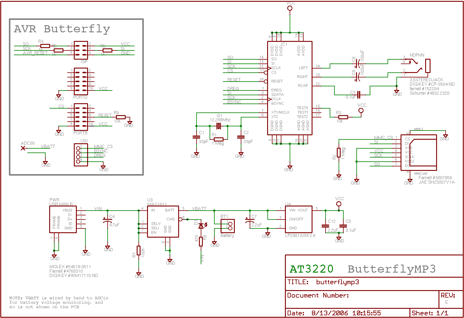
This page outlines the hardware and software design of a printer power switch that is controlled via USB from a Linksys NSLU2, also referred to as Slug. Although primarily designed for printer control, the unit can manage any device...
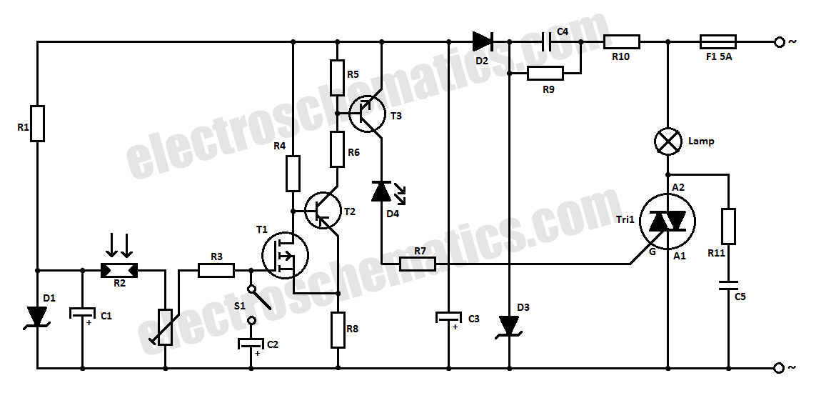
This halogen switch circuit utilizes a FET transistor, as the current is influenced by the gate voltage of the FET. The maximum gate voltage is 12V, making the circuit suitable for 12-volt lamps. The resistor R1 has a value...
This is a high-frequency switch circuit. This circuit utilizes the 2N4391 transistor. When in the off state, it provides a high off-impedance of less than 0.2 pF and exhibits a low on-resistance. The high-frequency switch circuit designed with the 2N4391...
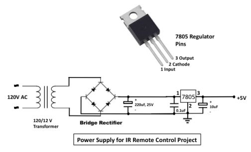
The infrared (IR) toggle switch project aims to provide a control mechanism for electrical appliances lacking remote operation features. The objective is to create a device that allows users to plug in a 120V AC appliance and control its...
Light Sensitive Switch is a simple project which operates a relay when the light falling on the LDR goes below a set point. More: Input - 12 V @ 55 mA Relay output - NC-C-NO Onboard preset to set the level Power-On...
When the phototransistor is struck by IR light, it conducts, and the voltage between the 1 MΩ resistor (arbitrary) and the phototransistor drops from VCC to lower values. When the voltage drops lower than VCC/3, the 555 is triggered...