
Ultrasonic Radar AlarmCircuit Project
When constructing electronic circuits on a printed circuit board (PCB), the board is typically made from a thin insulating material coated with a layer of conductive copper, which forms the necessary connections between components. A well-designed PCB is advantageous as it accelerates construction and minimizes errors. Smart Kit boards come pre-drilled with component outlines and identifications printed on the component side to facilitate assembly. To protect the PCB from oxidation during storage and ensure it arrives in optimal condition, the copper is tinned during manufacturing and coated with a special varnish that prevents oxidation and simplifies soldering.
Soldering components to the board is essential for circuit assembly, and the technique employed significantly impacts the success of the project. A lightweight soldering iron, with a maximum power of 25 Watts and a fine tip, is recommended. It is crucial to maintain a clean tip, which can be achieved using specially designed damp sponges to remove residue. Avoid filing or sanding a dirty or worn tip; if cleaning is ineffective, replace the tip. Selecting high-quality solder that contains the necessary flux in its core is important for creating reliable joints. Using additional soldering flux not included in the solder can lead to circuit malfunctions; if extra flux is necessary, it should be thoroughly cleaned after use.
To solder a component correctly, the following procedure should be followed: the hot iron's tip should be placed on the component lead while the end of the solder wire is held at the joint, allowing for proper melting and bonding of the materials.As it has already been stated the circuit consists of an ultrasonic transmitter and a receiver both of which work at the same frequency. They use ultrasonic piezoelectric transducers as output and input devices respectively and their frequency of operation is determined by the particular devices in use.
The transmitter is built around two NAND gat es of the four found in IC3 which are used here wired as inverters and in the particular circuit they form a multivibrator the output of which drives the transducer. The trimmer P2 adjusts the output frequency of the transmitter and for greater efficiency it should be made the same as the frequency of resonance of the transducers in use.
The receiver similarly uses a transducer to receive the signals that are reflected back to it the output of which is amplified by the transistor TR3, and IC1 which is a 741 op-amp. The output of IC1 is taken to the non inverting input of IC2 the amplification factor of which is adjusted by means of P1.
The circuit is adjusted in such a way as to stay in balance as long the same as the output frequency of the transmitter. If there is some movement in the area covered by the ultrasonic emission the signal that is reflected back to the receiver becomes distorted and the circuit is thrown out of balance.
The output of IC2 changes abruptly and the Schmitt trigger circuit which is built around the remaining two gates in IC3 is triggered. This drives the output transistors TR1, 2 which in turn give a signal to the alarm system or if there is a relay connected to the circuit, in series with the collector of TR1, it becomes activated.
The circuit works from 9-12 VDC and can be used with batteries or a power supply. First of all let us consider a few basics in building electronic circuits on a printed circuit board. The board is made of a thin insulating material clad with a thin layer of conductive copper that is shaped in such a way as to form the necessary conductors between the various components of the circuit.
The use of a properly designed printed circuit board is very desirable as it speeds construction up considerably and reduces the possibility of making errors. Smart Kit boards also come pre-drilled and with the outline of the components and their identification printed on the component side to make construction easier.
To protect the board during storage from oxidation and assure it gets to you in perfect condition the copper is tinned during manufacturing and covered with a special varnish that protects it from getting oxidised and also makes soldering easier. Soldering the components to the board is the only way to build your circuit and from the way you do it depends greatly your success or failure.
This work is not very difficult and if you stick to a few rules you should have no problems. The soldering iron that you use must be light and its power should not exceed the 25 Watts. The tip should be fine and must be kept clean at all times. For this purpose come very handy specially made sponges that are kept wet and from time to time you can wipe the hot tip on them to remove all the residues that tend to accumulate on it. DO NOT file or sandpaper a dirty or worn out tip. If the tip cannot be cleaned, replace it. There are many different types of solder in the market and you should choose a good quality one that contains the necessary flux in its core, to assure a perfect joint every time.
DO NOT use soldering flux apart from that which is already included in your solder. Too much flux can cause many problems and is one of the main causes of circuit malfunction. If nevertheless you have to use extra flux, as it is the case when you have to tin copper wires, clean it very thoroughly after you finish your work. In order to solder a component correctly you should do the following: @Take the hot iron and place its tip on the component lead while holding the end of the solder wire at the
🔗 External reference
Related Circuits
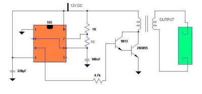
Fluorescent tubes contain mercury, which poses health risks. Improper disposal of these tubes is harmful to both the environment and health; therefore, recycling is a beneficial option. The 555 timer IC is utilized to generate a square wave voltage...
This ultrasonic anemometer is designed for the two-dimensional measurement of horizontal wind speed components and wind direction, as well as virtual temperature. Due to its high measurement rate, the device effectively captures gusts and peak values without delay. The...
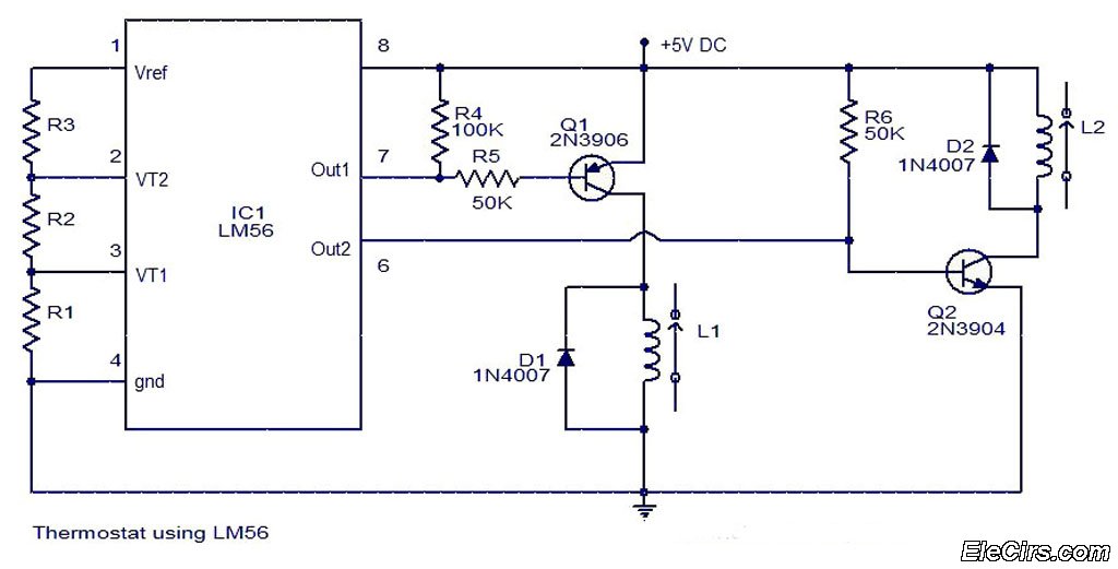
The LM56 Thermostat Project Circuit Diagram includes a schematic for the LM56 thermostat. The values of resistors R1, R2, and R3, which determine the required trip points VT1 and VT2, can be calculated using the following equations: VT1 =...
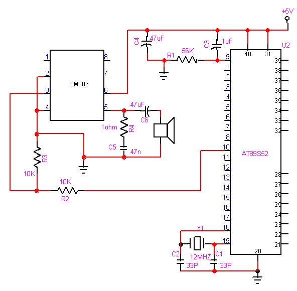
The 8051 microcontroller can play music tones. Here is a sample circuit and code that will play the music for "wishes you to be..." The 8051 microcontroller is a versatile and widely used microcontroller in embedded systems, capable of performing...
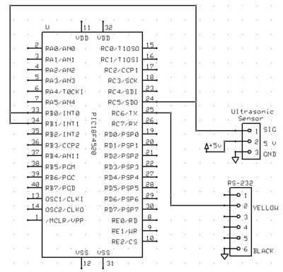
The Ping Ultrasonic Distance Sensor by Parallax features three pins: +5V, I/O, and Ground. To activate the sensor, a 5-microsecond 5V signal must be sent to the I/O pin. Following this, the sensor waits 750 microseconds before emitting an...
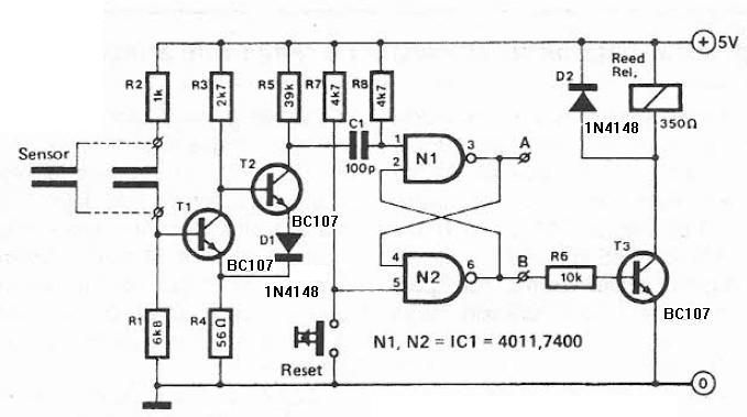
This humidity detector circuit diagram is straightforward and utilizes a limited number of components. It can be employed to activate electronic devices when the detector identifies a specific humidity level. The sensor is made from two copper pieces positioned...
Warning: include(partials/cookie-banner.php): Failed to open stream: Permission denied in /var/www/html/nextgr/view-circuit.php on line 713
Warning: include(): Failed opening 'partials/cookie-banner.php' for inclusion (include_path='.:/usr/share/php') in /var/www/html/nextgr/view-circuit.php on line 713