
simple fluorescent inverter project
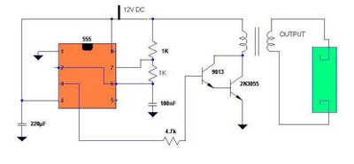
The circuit employs a 555 timer IC configured in astable mode to produce a continuous square wave signal at a frequency of approximately 4.8 kHz. This frequency is critical for efficient operation, allowing the circuit to provide a rapid on-off cycling that is necessary for the excitation of the gas within the fluorescent tube.
The primary winding of the transformer is constructed with 16 turns of #22 AWG wire. This winding is connected to the output of the 555 timer circuit, which drives the current through the primary coil. The resulting magnetic field generated by the primary winding induces a current in the secondary winding.
The secondary winding, made of 350 turns of #30 AWG wire, is designed to step up the voltage significantly. The ratio of turns between the primary and secondary windings (approximately 21.875:1) allows for a high-voltage output sufficient to strike the gas within the fluorescent tube. This is particularly advantageous for tubes with damaged filaments, as the high-voltage pulse can initiate the ionization process necessary for the tube to operate, even in the absence of a functioning filament.
The circuit's design also ensures that the current pulses generated in the primary winding are limited to approximately 4A, which is an optimal level for preventing overheating and ensuring the longevity of the components used. The use of appropriate wire gauges for both windings is crucial for maintaining efficiency and minimizing losses due to resistance.
In summary, this circuit provides an effective solution for recycling fluorescent tubes by utilizing a 555 timer IC to generate a high-frequency square wave, which drives a transformer to produce the necessary high voltage for tube ignition, thereby addressing both environmental concerns and health risks associated with improper disposal.As we know, fluorescent tube contains mercury that is dangerous to health. improper disposal of this tube is not good to environment and to health, thus recycling is a good choice. The use of 555 timer IC is to generate square wave voltage of about 4. 8kHz and the the primary winding (16 turns of #22 AWG) will generate current pulses of about 4A, an d in return will induce a a high voltage at the secondary winding (350 turns of #30 AWG) of the inverter. This voltage is enough to strike the fluorescent tube even if the filament is not heated thus very suitable to tubes with broken filaments ( burnt out filaments).
🔗 External reference
Related Circuits
The LM56 Thermostat project circuit diagram involves determining the values of resistors R1, R2, and R3 for the temperature points VT1 and VT2 using specific equations. This electronic circuit featuring the IC LM56 serves as a simple reference project....
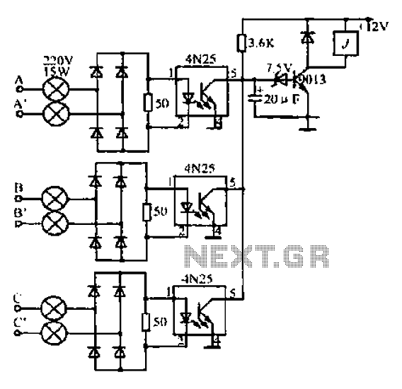
A, B, and C are used for a large power split-phase system. The A + BC range generator phase line features an A-A indole path string containing two 220V/15W bulbs. The bulbs recover based on macro instructions from J...
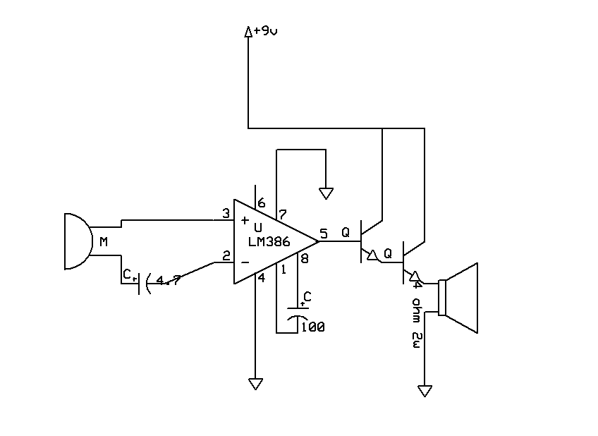
The sound quality was poor, and then it stopped functioning. Can anyone explain which part of the circuit may have malfunctioned? Any suggestions to enhance the sound quality and restore functionality? The transistors used are both BC546, and the...
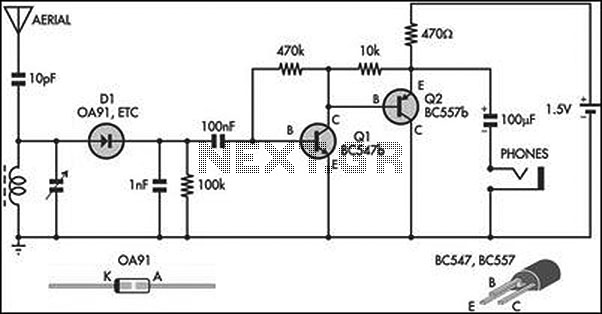
This circuit is an amplified crystal set. The inductor can be a standard AM radio ferrite rod antenna, while the tuning capacitor is a variable plastic dielectric gang designed for small AM radios. The aerial tuned circuit feeds diode...

This optodetector measures the position of the ball by the amount of light transmitted by the infrared LED. It generates a linear signal across the small area of the detector, rather than simply providing an "on" or "off" output....
I designed a simple sinewave generator based on a Analog Devices AD9832 chip. It will generate a sinewave from 0.005 to 12 MHz in 0.005 Hz steps. That's pretty good, and definitely good enough for me! But while waiting...
Warning: include(partials/cookie-banner.php): Failed to open stream: Permission denied in /var/www/html/nextgr/view-circuit.php on line 713
Warning: include(): Failed opening 'partials/cookie-banner.php' for inclusion (include_path='.:/usr/share/php') in /var/www/html/nextgr/view-circuit.php on line 713