
Ultrasonic Range & Imager

The SONAR system operates by alternating the function of the piezoelectric transducer, allowing it to emit ultrasonic waves and subsequently listen for echoes. The four 4016 analog switches facilitate this switching process, ensuring that the transducer can rapidly toggle between TX and RX modes without significant delay. The high-gain amplifier stage is crucial for amplifying the weak signals received from distant objects, enabling the detection of echoes that may otherwise be too faint to discern. The rectifier converts these amplified signals into a usable voltage form for further processing.
The PIC12C508 microcontroller plays a vital role in managing the timing and control of the entire SONAR system. By executing programmed instructions, it ensures that the sampling rate of 18 kHz is maintained, allowing for accurate capture and processing of the echo data. The 68HC11 prototype board serves as the primary interface for data acquisition, where the analog input channel receives the voltage pulses corresponding to the detected echoes.
The mechanical scanning of the SONAR is facilitated by a stepper motor, which allows for precise angular movements and thus broadens the detection area. The use of a paper horn to focus the ultrasonic beam enhances the system's directionality, reducing beam divergence and improving the resolution of distant objects. However, the trade-off is an increase in back reflections, which complicates the interpretation of close-range echoes. This phenomenon illustrates the challenges faced in SONAR design, where optimizing for one parameter can adversely affect another.
Overall, the described SONAR system demonstrates an innovative approach to distance measurement and object detection using a combination of analog and digital technologies, showcasing the intricate balance between various design elements to achieve effective performance.This is the electronic schematic of the homebuilt SONAR. Only one piezoelectric transducer is used for both transmit & receive. This transducer is switched from TX to RX via the four 4016 switches. A high gain amplifier stage & rectifier translates the received echoes into voltage pulses. The timing is controlled by the PIC12C508 8-pin microcontro ller as it is shown in the following figure: The SONAR system is connected to an analog input of a 68HC11 prototype board. The echoes are sampled at about 18KHz, with 8 bit resolution. The captured data looks like this: The starting decay is due to the residual transducer oscillation. This decay limits the minimum range of the SONAR to about 50 cm. The peak around sample 230 is due to a wall echo. The wall was located 2. 5m away from the SONAR. The next graph shows the echo of a close obstacle (me :) Two successive scans are shown: Then, the SONAR was mechanically scanned with the help of an stepper motor controlled by the 68HC11.
The transmitted beam was also focused through a paper horn. The results were: With the use of this lens the beam divergence was greatly reduced, but another problem arises: a notable fraction of the ultrasonic power is reflected back, causing undesired echoes that can be misinterpreted in the short range. The following graph shows the results obtained with the lens. The close echoes in the left are in fact back echoes. In the other hand, the distant echoes are a lot better resolved. 🔗 External reference
Related Circuits
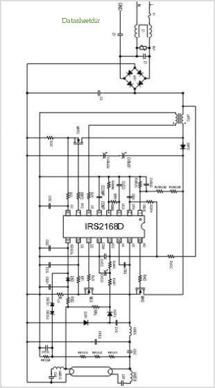
A circuit diagram for an animal repeller is provided. The circuit has been developed but is not functioning as intended. Assistance is requested for troubleshooting. The animal repeller circuit typically employs ultrasonic sound waves to deter animals from specific areas....
ISL83202IPZ is a subpackage of ISL83202. For the full description, please refer to ISL83202. The datasheet for ISL83202IPZ can be downloaded from the link provided below. By Intersil Corporation. The ISL83202IPZ is a component within the ISL83202 series, designed for...
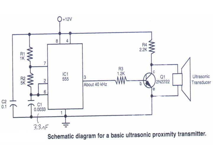
This section provides step-by-step instructions along with images for constructing an Ultrasonic Proximity Transmitter. Due to the simplicity of the circuit, only a schematic for the sensor is presented here. The objective of this tutorial is to assist others...
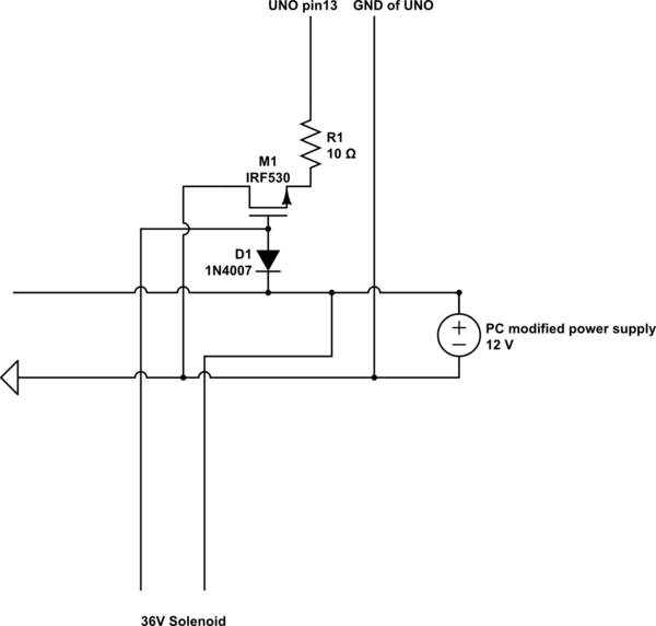
A 9 V DC battery initially powered the solenoid valve effectively. However, the solenoid did not generate sufficient force due to inadequate DC power. A modification was made to use a computer power supply as the power source. Providing...
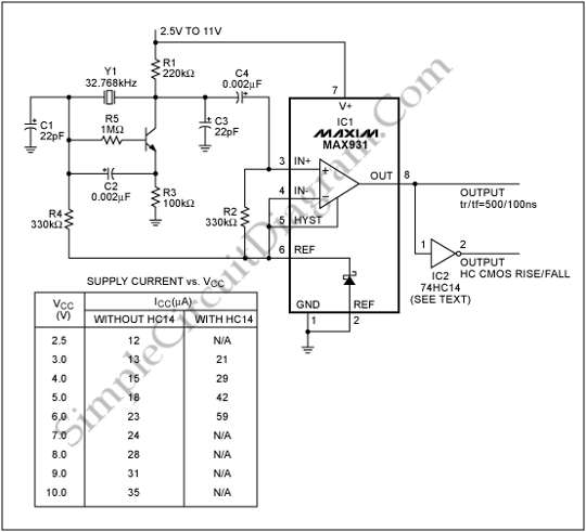
To generate a system clock or auxiliary sleep clock in microcontrollers (µCs) and low-power instruments, a 32 kHz oscillator is commonly utilized. This oscillator typically employs a CMOS inverter. A 32 kHz oscillator is essential for various timing functions in...
A variable audio oscillator operates within a frequency range of 20 hertz to 20 kilohertz. The circuit utilizes an Intersil 8038 waveform generator, which is designed in a 14-pin dual in-line package (DIP). The variable audio oscillator circuit is designed...