
ultrasonic transmitter
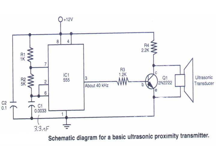
The Ultrasonic Proximity Transmitter is designed to emit ultrasonic waves that can be detected by an ultrasonic receiver. This basic circuit typically consists of a few key components: an ultrasonic transducer, a microcontroller or oscillator circuit, and necessary passive components such as resistors and capacitors. The transducer converts electrical signals into ultrasonic sound waves, which propagate through the air.
The schematic representation of the circuit will include the ultrasonic transducer connected to a microcontroller. The microcontroller generates a square wave signal, which is fed to the transducer. This signal determines the frequency of the emitted ultrasonic waves, commonly around 40 kHz for proximity sensing applications.
In addition to the transducer and microcontroller, the circuit may incorporate a power supply section to ensure stable operation. This can be achieved using a battery or a regulated power supply. Decoupling capacitors are often included to filter out noise and provide a stable voltage to the microcontroller.
The construction process involves carefully assembling the components on a breadboard or PCB, following the schematic. The tutorial provides detailed images to guide through each step of the assembly, ensuring that connections are made correctly and securely.
Once the assembly is complete, the device can be tested by measuring the distance to an object using the time it takes for the emitted ultrasonic waves to reflect back to the transducer. This functionality allows the ultrasonic proximity transmitter to be integrated into robotic systems, enabling them to navigate and avoid obstacles effectively.
Overall, this project not only demonstrates the principles of ultrasonic sensing but also provides a practical application in robotics, enhancing the capabilities of autonomous systems.This section gives step-by-step instructions along with photos to the construction of Ultrasonic Proximity Transmitter. Because this is a very simple circuit, only a schematic for the sensor is shown here: (For the PDF format click here.
) This tutorial`s objective was to help others built a ultrasonic proximity transmitter which combined with a ul trasonic receiver will be used as the eyes of a robot. Complete construction details and photos are included in this tutorial for the sensor. Once the concepts are conveyed the reader should be able to build their own sensor. 🔗 External reference
Related Circuits
This schematic represents a tone transmitter. When using sufficiently small resistor values, it generates a tone. A resistive microphone (such as a carbon microphone) can be placed in parallel with or replace the resistor, allowing modulation of the tone...
The motion sensor circuit depicted in Figure 1 operates when a 12-volt power supply is applied to the input point. The motion sensor circuit is designed to detect movement and trigger a response based on the presence of motion...
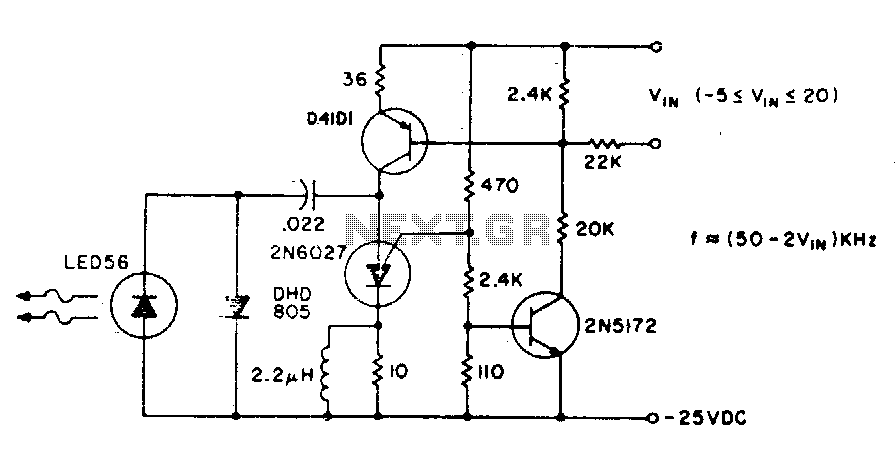
The basic circuit operates at a frequency of 80 kHz, which is constrained by the combination of the PUT (Programmable Unijunction Transistor) capacitors. The maximum modulation frequency achievable is 60 kHz. The pulse repetition rate is directly proportional to...
This small transmitter employs a Hartley-type oscillator. Typically, the capacitor in the tank circuit connects to the base of the transistor; however, at VHF frequencies, the base-emitter capacitance of the transistor behaves like a short circuit, maintaining effective operation....
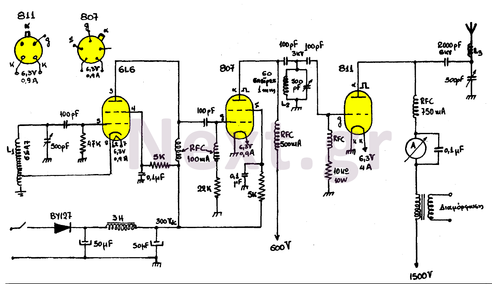
This transmitter consists of three stages: the oscillator stage utilizing a 6L6 tube, the amplifier isolator stage with an 807 tube, and the final stage of the transmitter featuring an 811 tube. The coil L1 is specified by the...
This is an AM transmitter schematic diagram. The circuit is divided into two halves: an audio amplifier and an RF oscillator. The oscillator is constructed around Q1 and its associated components. The tank circuit, consisting of L1 and VC1,...