
Universal frequency meter
The frequency meter operates within a specified frequency range of 10 Hz to 1300 MHz, utilizing a PIC16F84 microcontroller as its core processing unit. The design divides the frequency measurement into two distinct ranges: 10 Hz to 25 MHz and 25 MHz to 1300 MHz, allowing for optimized performance across these bands. The decimal point in the display can be configured to show values in a user-friendly manner, typically positioned after the MHz digit.
The system employs several key components, including the 74HC137, which serves as a BCD to 1-of-8 decoder, facilitating the conversion of binary-coded decimal inputs into a format suitable for the display. The SAB6456 is integrated as a VHF-UHF divider with a division factor of 256, effectively scaling down the input frequency to a manageable level for the PIC microcontroller.
The display mechanism utilizes a 7-digit common cathode LED multiplexed display, which is suitable for visualizing the frequency readings. The software controlling the display is specifically designed for common cathode configurations; modifications would be necessary for compatibility with common anode displays.
The PIC16F84 is configured as a 3-byte counter, where the maximum frequency that can be measured is theoretically 167.77215 MHz, although practical limitations reduce this to around 25-30 MHz due to various factors such as signal integrity and processing speed. The internal prescaler of the PIC is utilized as the low byte of the counter, while Timer0 (TMR0) functions as the middle byte, and an additional register is employed as the high byte. This architecture allows for efficient counting and processing of input frequencies.
Notably, the software is designed to operate without reading from any input ports, simplifying the control logic. The RA4 pin is designated as the prescaler input, ensuring that the frequency data is accurately captured and processed by the microcontroller. Overall, this frequency meter design represents a robust solution for frequency measurement across a wide range of applications, leveraging both hardware and software components effectively.This is 7-digit frequency meter measuring frequency from 10 Hz up to 1300 MHz. It is based on ideas of PIC16F84 based frequency meter. The measuring range is divided into two subranges: 10Hz - 25MHz and 25 MHz - 1300MHz. The decimal point is after MHz digit, but can be set at any position.
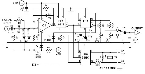
It contains: PIC 16F84 74HC137 (BCD -> 1 of 8 decoder) SAB6456 VHF-UHF divider by 256 7-digit calculator display (common cathode), some resistors, capacitors and 2 switching diodes Note: "Calculator display" means (say) 7 digit LED multiplexed display. Common cathode display is used. Software is written for common cathode. For common anode displays it requires some software and hardware modification . PIC is used as 3 byte counter. If it counts 0.1 s maximum measured frequency is FF FF FF, e. g. 167.77215 MHz (theoretically) - practically 25 - 30 MHz. SAB6456 is used as 1:256 predivider. Its upper limit is 1300MHz. The device uses internal prescaler of PIC as low byte of counter, TMR0 as middle byte and some register as high byte of counter.
The software DOESN'T read anything from any input port. RA4 is used as prescaler input.
Related Circuits
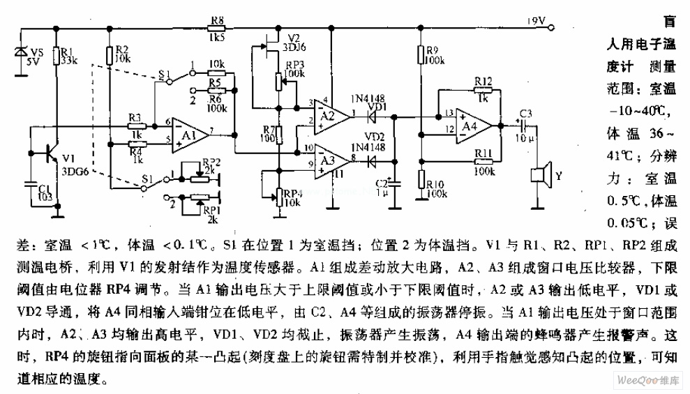
Measuring range: room temperature is -10 to 40 degrees Celsius; body temperature is 36 to 41 degrees Celsius; Resolution: room temperature is 0.5 degrees Celsius, body temperature is 0.05 degrees Celsius; error: room temperature <1 degree Celsius, body temperature <0.1 degrees Celsius. When switch S1 is in position 1, it displays the room temperature profile; position 2 displays the body temperature profile. Components V1, R1, R2, RP1, and RP2 form the temperature measurement circuit. The temperature measurement circuit is designed to monitor and display two distinct temperature ranges: ambient room temperature and body temperature. The circuit operates with a measuring range for room temperature from -10 to 40 degrees Celsius and for body temperature from 36 to 41 degrees Celsius. The resolution of the circuit is fine-tuned to provide accurate readings, with a room temperature resolution of 0.5 degrees Celsius and a body temperature resolution of 0.05 degrees Celsius. The specified error margins indicate a maximum deviation of less than 1 degree Celsius for room temperature measurements and less than 0.1 degrees Celsius for body temperature measurements. The circuit utilizes a switch, S1, which allows the user to select between the two temperature profiles. In position 1, the circuit outputs the room temperature, while in position 2, it outputs the body temperature. The operational components include a voltage source (V1), resistors (R1, R2), and potentiometers (RP1, RP2) that are integral to the measurement process. Resistors R1 and R2 are likely part of a voltage divider network that aids in scaling the temperature sensor output to a readable format. Potentiometers RP1 and RP2 can be used for calibration purposes, allowing fine adjustments to ensure that the readings are accurate within the specified error margins. The temperature sensor, which is not explicitly mentioned but is assumed to be part of the circuit, converts temperature changes into an electrical signal that can be processed by the circuit. The output from the sensor is conditioned by the resistive components to produce a voltage level that corresponds directly to the measured temperature. This voltage is then displayed on an appropriate display unit, which could be an analog gauge or a digital readout, depending on the design of the circuit. Overall, this temperature measurement circuit is a practical solution for monitoring both ambient and body temperatures with high accuracy and user-friendly operation through the selection switch.
The following circuit enables measurement of the inductance of the inductor labeled LX, which is the inductance to be measured. The output of the circuit is a TTL square wave whose frequency relates to the inductance being measured. The...

The circuit is based on an LM3914N bar graph display driver device (IC1), which can be used to drive up to ten LEDs. This is connected so that with OV12 at the input only the first LED indicator switches...
This frequency counter utilizes an existing digital multimeter (DMM) as the display unit, allowing for a low-cost construction. Due to the high impedance characteristic of most DMMs, a frequency-to-voltage converter can be easily connected without matching issues. The converter...
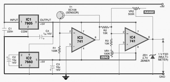
This DIY digital thermometer circuit can measure temperatures up to 150°C with an accuracy of ±1°C. The temperature is displayed on a 1V full scale deflection. The digital thermometer circuit is designed to provide accurate temperature readings within a specified...
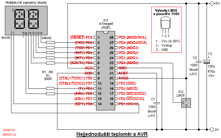
This is a simple digital thermometer utilizing an Atmel AVR microprocessor, capable of measuring temperatures in the range of 2 to 99 °C with a resolution of 1 °C. The circuit is managed by an Atmel AVR ATmega8, ATmega8L,...