
Univibe - Trem Face and Others
The described circuit focuses on a univibe effect, which is a modulation effect commonly used in electric guitar applications. The key component is the dual section reverse log taper potentiometer, which functions as two variable resistors. This configuration allows for precise control over the modulation depth and speed. The use of an LED and a dual light-dependent resistor (LDR) module, such as the VT5C3/2, enables the modulation characteristics to be adjusted dynamically based on light levels.
In the circuit, a transistor is employed to regulate the current flowing through the LDR, influencing the response of the modulation effect. The single 10K potentiometer for speed control adjusts the current through the LED, which in turn affects the brightness and the resulting modulation effect. The voltage across the LED is determined by the V+ supply voltage, minus the forward voltage drop of the LED and the base-emitter voltage (Vbe) of the transistor. This setup allows for a customizable range of modulation speeds, which can be fine-tuned by selecting appropriate resistor values for Re, based on the desired maximum LED current.
The circuit also includes resistors to set minimum and maximum resistance values, ensuring that the modulation remains within a usable range. This design can be adapted for use in other modulation effects, such as tremolo circuits. Specifically, in the Trem Face design, a voltage-driven phase shift oscillator serves as the low-frequency oscillator (LFO). By replacing the dual pot with the transistor and LDR setup, the modulation speed becomes voltage-controlled, allowing for external control via expression pedals or synchronization with other effects.
This voltage control capability enhances the versatility of the circuit, enabling it to respond to various control voltages, such as those from envelope detectors or random voltage generators. By varying both resistors in the phase shift oscillator, a broader range of modulation speeds can be achieved, providing more creative possibilities for sound design.Where it really shines is in the univibe. The 'vibe uses a dual section, reverse log taper pot that's just a bit easier to find than a dinosaur's tooth. If we notice that the pot is really wired as two variable resistors, we can use an LED/dual LDR module like the VT5C3/2, which costs about $5 from Newark and other electronics distributors.
To give us good control, we use a transistor to vary the LDR current. With a single 10K pot for speed, the transistor varies the current in the LED from nearly off to a voltage set by the V+ voltage minus the LED 1 voltage and the Vbe of the transistor. You take that voltage, divide by the max current you want in your LED, and insert that resistance into Re.
The 'vibe circuit has resistors to limit the min and max resistance the circuit sees. I did this in my tube univibe, and it works great. You can mess with the taper of the single speed resistor (See The Secret Life of Pots) to adjust the effective taper of the speed control pot as you like it. Here's how to add the same thing onto a tremolo. The Trem Face is a nonstandard kind of trem, but it uses a voltage-driven version of the phase shift oscillator for an LFO. Again, cut out the dual pot, and replace it with the transistor/pot/VT5C3/2. In this design, you may want to remove LED1 to give yourself a little more voltage variation on the speed pot.
Here's how to hook it into the EAN tremolo. "But wait!" I hear you saying, "The EAN tremolo doesn't use a dual pot!" Notice that once you have this set up, the speed is voltage controlled. You can feed a voltage into the base of the transistor and the speed of the oscillator will follow it.
Useful things to do this with are (1) expression pedals (2) a synchronizing signal for operating multiple pedals in synchrony (3) an envelope detector (4) a random voltage generator similar to one of the ones in the Pseudorandom LFO article here on GEO. That's correct. The designer settled for the limited oscillation range they could get by varying only one of the two resistors available for controlling speed in the phase shift oscillator.
By varying both, you get a much wider range of control from slowest to fastest. 🔗 External reference
Related Circuits
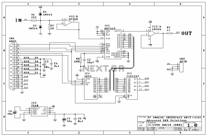
The Analog Interface Unit (AIU) is a simple circuit that connects to a PC parallel port, and allows you to sample and output 8-bit analog signals under software control. More: Here are some of the features: 8-bit ADC and...
Many microcontroller designs typically integrate various interfacing methods. A microcontroller (µC) system can be viewed as a system that reads from inputs. Microcontroller systems are versatile platforms that facilitate the integration of multiple interfacing methods to interact with various peripherals...
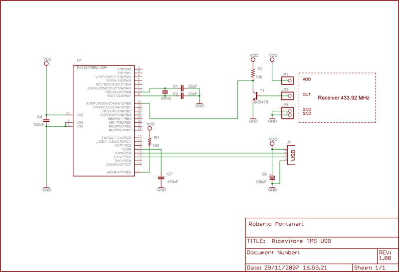
This thread explains the creation of a custom USB tire pressure monitoring system by modifying an aftermarket kit purchased on eBay. The initial step involved... The project entails the design and implementation of a USB tire pressure monitoring system (TPMS)...
Watching the time on a mobile phone in the dark can cause discomfort due to the strong contrast between bright and dark backlighting. To address this issue, the "ICON" model is utilized, which operates in standby mode with a...
This interface circuit provides electrically isolated RS422 communication interface to the PC serial port. The isolation circuit protects the PC from direct connection to hazardous voltages. More: Figure 1 shows the circuit diagram of RS422 interface. Connector K1 is...
It is very useful for 1 -100 watt AUDIO AMPLIFIERS This description refers to a component or circuit designed to enhance the performance of audio amplifiers in the power range of 1 to 100 watts. Such amplifiers are commonly used...