
Microcontroller Relay Driver and Interface

Microcontroller systems are versatile platforms that facilitate the integration of multiple interfacing methods to interact with various peripherals and components. These systems often employ digital and analog inputs and outputs to manage tasks ranging from simple control operations to complex data processing.
In a typical microcontroller schematic, the microcontroller unit serves as the central processing unit (CPU), which executes programmed instructions and manages the flow of data between different interfacing modules. Common interfacing methods include GPIO (General Purpose Input/Output) pins, ADC (Analog to Digital Converters), PWM (Pulse Width Modulation), and communication protocols such as I2C, SPI, and UART.
The schematic usually features power supply connections that provide the necessary voltage levels to the microcontroller and associated components. It also includes decoupling capacitors placed near the power pins of the microcontroller to stabilize the power supply and filter out noise.
Input devices such as sensors and switches are connected to the microcontroller's input pins. These devices can provide digital signals (on/off states) or analog signals (varying voltage levels), which the microcontroller processes based on its programmed logic.
Output devices, such as LEDs, motors, or displays, are connected to the output pins, allowing the microcontroller to control these components based on the input data it receives. Additionally, communication interfaces enable the microcontroller to communicate with other devices or systems, enhancing the overall functionality of the design.
In summary, a microcontroller system's schematic encompasses a well-organized arrangement of various interfacing methods, ensuring seamless interaction between the microcontroller and its peripheral devices, thereby enabling complex tasks to be performed efficiently.Many microcontroller designs typically mix multiple interfacing methods. A microcontroller (µC) system can be viewed as a system that reads from inpu.. 🔗 External reference
Related Circuits
This article discusses the design of an LED driver for automotive rear lights. It demonstrates that dimming is most effectively accomplished using pulse-width modulation (PWM) in conjunction with an LED driver integrated circuit (IC) that removes the requirement for...
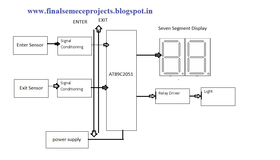
This project involves an automatic room light controller with a bidirectional visitor counter using a microcontroller. It is designed to manage room lighting and accurately count the number of individuals present. When a person enters the room, the counter...
The Xminilab-B oscilloscope is based on the Atmel AVR ATXMEGA32A4 microcontroller. It is designed as a debug board by the Gabotronis company, as noted on rlocman.ru. The Xminilab-B oscilloscope features a compact and efficient design that leverages the capabilities of...
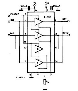
The IC H-Bridge DC motor driver L298 contains two H-Bridge circuits, allowing it to drive two DC motors simultaneously. Each H-Bridge circuit can deliver currents up to 2A. When used in parallel, the L298 can provide a total current...
Standard serial interfacing of a microcontroller (TTL) with a PC or any RS232C standard device requires a TTL to RS232 level converter. A MAX232 is used for this purpose. It provides a 2-channel RS232C port and requires external 10µF...
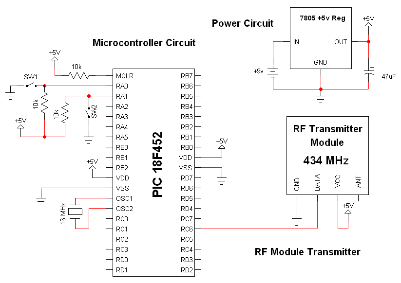
The RF modules utilized in this schematic are straightforward, requiring only a few additional pins for power, ground, and data connections. The primary components featured in this schematic include the RF transmitter module, the RF receiver module, and the...