
USART + Serial Comm with PC
The project involves establishing serial communication between a microcontroller and a personal computer (PC) using the Universal Synchronous/Asynchronous Receiver-Transmitter (USART) interface. The primary objective is to send a basic "Hello World" message from the microcontroller to the PC, allowing for verification of the communication setup.
To implement this, the following components and steps are necessary:
1. **Microcontroller Selection**: Choose a microcontroller that supports USART functionality. Common options include the ATmega series, PIC microcontrollers, or STM32 families.
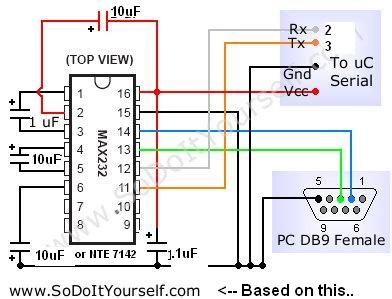
2. **Circuit Design**:
- Connect the microcontroller's TX (transmit) pin to the RX (receive) pin of a USB-to-serial converter or directly to the PC's serial port if available.
- Connect the microcontroller's RX pin to the TX pin of the USB-to-serial converter.
- Ensure common ground between the microcontroller and the PC for proper signal integrity.
3. **Software Configuration**:
- Initialize the USART module on the microcontroller. This involves setting the baud rate, character size, stop bits, and parity as per the requirements of the PC's serial communication settings (commonly 9600 baud, 8 data bits, no parity, and 1 stop bit).
- Write a simple program to send the string "Hello World" through the USART. This typically involves loading the string into a buffer and using the USART transmit function in a loop to send each character.
4. **Testing the Setup**:
- Use a terminal program on the PC (such as PuTTY, Tera Term, or the Arduino Serial Monitor) to open the corresponding COM port.
- Set the terminal settings to match the microcontroller's USART configuration.
- Upon powering the microcontroller, the terminal should display the "Hello World" message, confirming successful communication.
This basic setup serves as a foundational example for understanding serial communication using USART and can be expanded for more complex applications involving data exchange between the microcontroller and the PC.Create simple Hello world example of serial comm to a PC using microcontroller USART. 🔗 External reference
Related Circuits
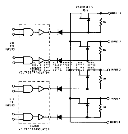
The DS7800 voltage translator is a monolithic device that provides a gate drive voltage ranging from 10 V to -20 V for JFETs while simultaneously ensuring DTL/TTL logic compatibility. This 4-channel commutator utilizes the 2N4091 to achieve a low...
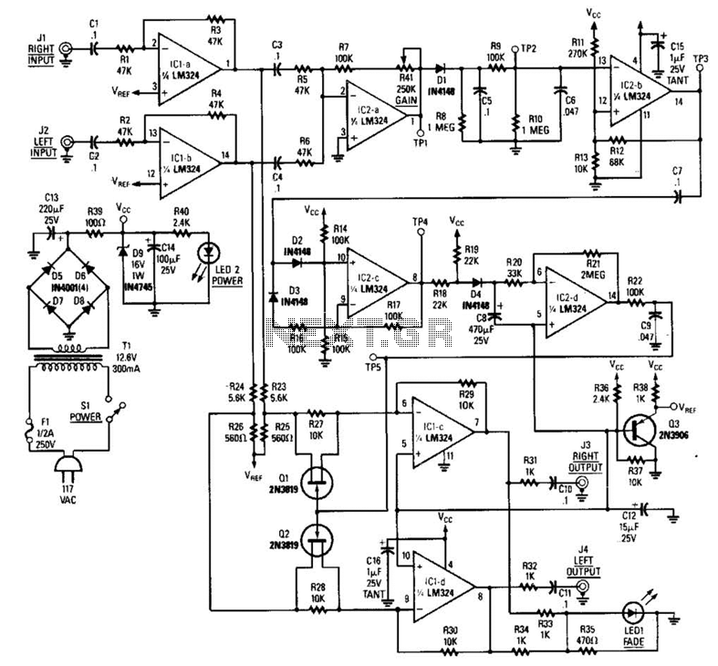
The LR inputs are summed, processed, and then drive a comparator. This comparator detects levels and generates transitions when audio inputs exceed or fall below predetermined thresholds. The frequency of these transitions, which correspond to rapid volume changes, is...
Xpressnet is a bus system designed for model railways, facilitating the interconnection of input devices, computer interfaces, stationary decoders, and feedback detectors. Numerous commercial input devices, such as the multi-mouse from Roco, utilize this bus system. An adapter is...
This circuitry facilitates the connection between the computer's Z RS-23 serial interface and the current ring circuitry. It converts the voltage signal of the transmission into a current signal of 20 mA, achieving a maximum speed of 1200 bits....
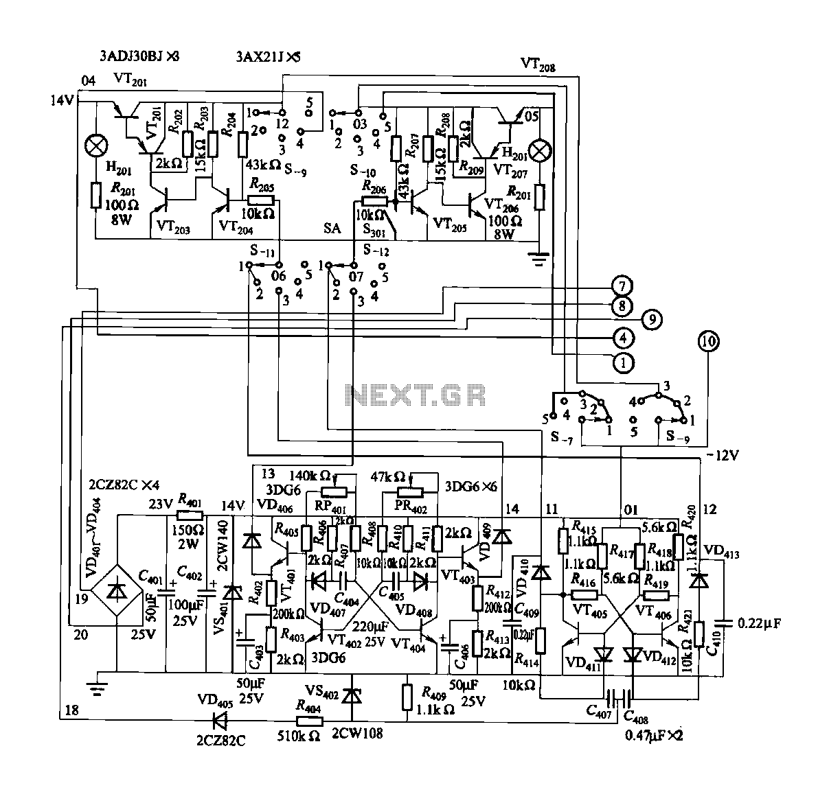
FGDF-3 is a three-phase low-temperature iron plating power commutation control switch and electronic circuit. The KGDF-3 serves as a low-temperature iron plating power supply device, incorporating the characteristics of a single-phase low-temperature iron plating power supply. This design facilitates...
This circuit diagram represents a laser communication system that transmits sound or music signals using a laser beam. The intensity of the laser beam varies in accordance with the amplitude of the sound signal. This variation in laser intensity...