
usb audio interface circuit based dac
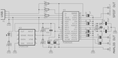
The described preamplifier circuit integrates a USB Digital-to-Analog Converter (DAC) with essential features for high-fidelity audio playback. The PCM2902 IC serves as the core of the circuit, providing a seamless interface between digital audio sources and analog output. The inclusion of both DAC and ADC capabilities allows for versatile audio handling, accommodating both playback and recording applications.
The power supply design utilizes the LP2951CM voltage regulator, which is known for its low dropout voltage, ensuring that the DAC receives a stable and clean power supply. This is critical for maintaining audio quality, as fluctuations in power can introduce noise and distortion. The output voltage of approximately 3.7V is achieved through a resistor divider, optimizing performance for the DAC's operational requirements.
The PCB layout is meticulously designed to minimize interference between analog and digital signals. Proper grounding techniques are employed to prevent ground loops and ensure a clean signal path. The single-point ground connection at the USB connector is a common practice to maintain signal integrity.
The recommendation for a Low Pass Filter (LPF) is crucial in audio applications to eliminate high-frequency noise that can occur during the oversampling process. The digital LPF within the PCM2902 is effective up to 100kHz, but additional filtering is advisable to further refine the output signal. The choice of a simple RC filter with a 1kΩ resistor and a 4.7nF capacitor provides a straightforward solution to attenuate unwanted frequencies, while the suggestion to use a roll-type capacitor ensures better performance compared to ceramic types.
Overall, this preamplifier circuit is designed with a focus on high-quality audio output, utilizing proven components and techniques to deliver a reliable and effective solution for audio amplification needs. The flexibility of the circuit allows for adjustments in filtering characteristics, accommodating various audio setups and preferences.This is high quality Preamplifier circuit with built-in USB DAC for my power amplifier Leachamp. Schematics is from datasheet of PCM2902. Circuit includes DAC and ADC, SPDIF output and input and HID part with 3 buttons for MUTE, VOL + and VOL-. For high quality playback is needed to use an external low-drop voltage stabilizer for the DAC part. DAC is used LP2951CM which was easily available at local stores. Output voltage is set to about 3. 7V with two resistors. Circuit board is designed regarding to good ground placement and separating of analog and digital ground. These ground are connected in one point at a USB connector. In datasheet of PCM2902 is recommended to connect Low Pass Filter to output of DAC for filtering high frequencies above audioband which are produced by oversampling conversion.
Integrated circuit includes digital LPF which filters frequency above 100kHz. In application notes for filter on the manufacturer pages are recommended 1st-Order LPF (simple RC) or 2nd-Order with operation amplifiers which works like preamplifier too. I used simple RC LPF with recommended values R 1k and C 4n7. It`s better to use roll-type capacitor instead ceramic. I didn`t hear difference in a sound between connection with filter or without it, but with respect to other components in a audio chain it is better to use it.
For a higher cut-off frequency we can change value of capacitor to 3n3. 🔗 External reference
Related Circuits
This stereo noise blanker or suppressor attenuates noise by 45 dB when the music signal is low or absent; it functions primarily as a noise limiter. The noise blanker sensitivity... This circuit serves as a stereo noise blanker or suppressor,...
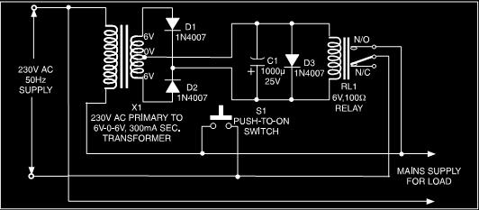
This is a low-cost protection circuit designed to safeguard electrically operated home appliances, such as TVs, DVD players, refrigerators, and other devices, during sudden power outages and the subsequent restoration of mains supply. Appliances like refrigerators and air conditioners...
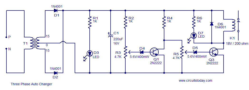
This circuit is a modification of a high and low voltage cut-off with delay and alarm circuit that was featured in Circuits Today. It has been tested and found to be reliable. The circuit can be adapted with minor...
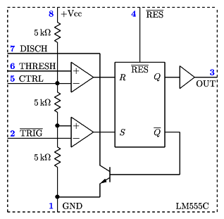
It is a typical Astable Multivibrator (AMV) setup. The capacitor charges through both resistors until it reaches 2/3 of Vcc, which is the level of the internal comparator. This triggers a flip-flop, activating the Discharge output (DIS). The capacitor...
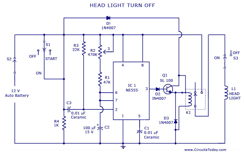
A circuit that can automatically turn off the headlights or lamps of a vehicle after a preset time. This light switching circuit is constructed using a 555 timer integrated circuit (IC). The described circuit utilizes the 555 timer IC in...
This project originated as an effort to create an inexpensive phono stage for an old turntable equipped with a low-cost cartridge using available components. However, it evolved into a noteworthy project that significantly enhances the overall analog setup. The...