
Automatic Head Lights Turn Off Circuit

The described circuit utilizes the 555 timer IC in a monostable configuration to achieve the automatic switching of vehicle headlights. In this setup, the 555 timer is triggered by a momentary switch, which could be activated when the driver turns off the ignition or exits the vehicle.
Upon triggering, the timer initiates a timing cycle determined by external resistors and capacitors connected to its timing pins (pin 6 and pin 2). The output (pin 3) of the 555 timer goes high for a duration defined by the time constant, which is calculated using the formula T = 1.1 * R * C, where T is the time in seconds, R is the resistance in ohms, and C is the capacitance in farads.
During this time, the output can drive a relay or transistor that controls the power to the vehicle's headlights, effectively turning them off after the preset time has elapsed. The circuit may also include a diode across the relay coil to prevent back EMF from damaging the 555 timer when the relay is de-energized.
Additional components such as capacitors may be added to stabilize the circuit and prevent false triggering due to noise. The design can be adjusted for various time intervals by selecting appropriate resistor and capacitor values, making it versatile for different vehicle applications.
This automatic headlight turn-off system enhances vehicle safety by ensuring that lights do not remain on unintentionally, thereby preventing battery drain and potential electrical issues.A circuit that can turn off head lights/lamps of a car/vehicle automatically after a preset time.This light switching circuit is built using 555 timer IC. 🔗 External reference
Related Circuits
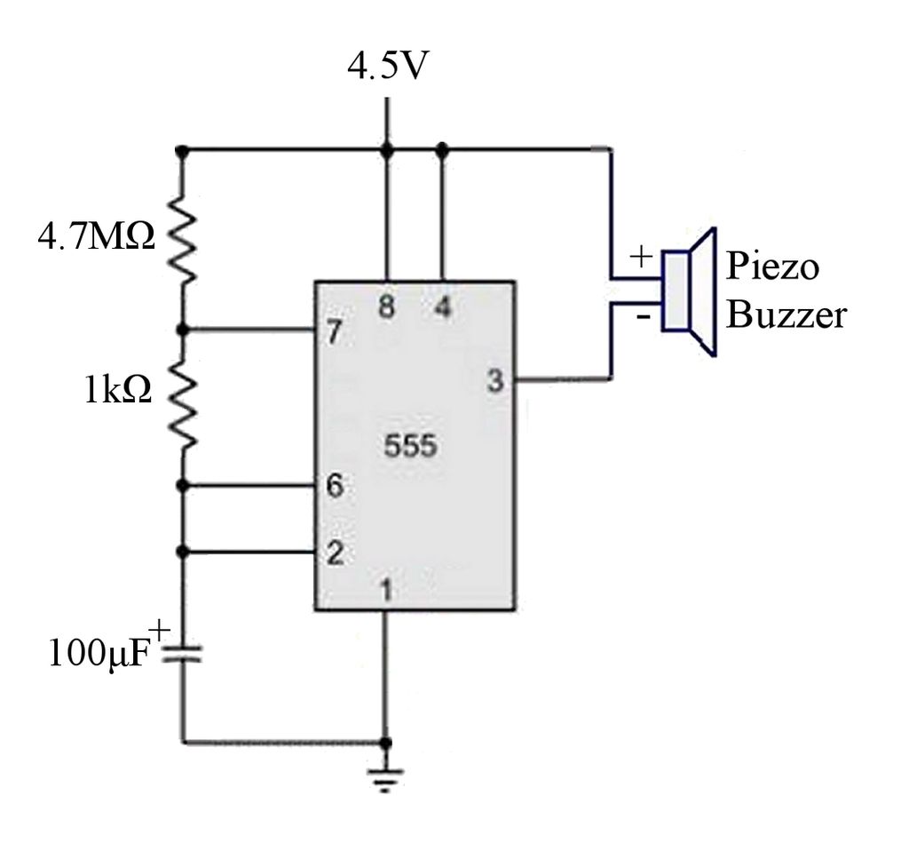
The circuit is a basic 555 timer circuit in astable mode. In this configuration, the integrated circuit (IC) generates a brief pulse to the buzzer at regular intervals. The 555 timer in astable mode operates as an oscillator, producing a...
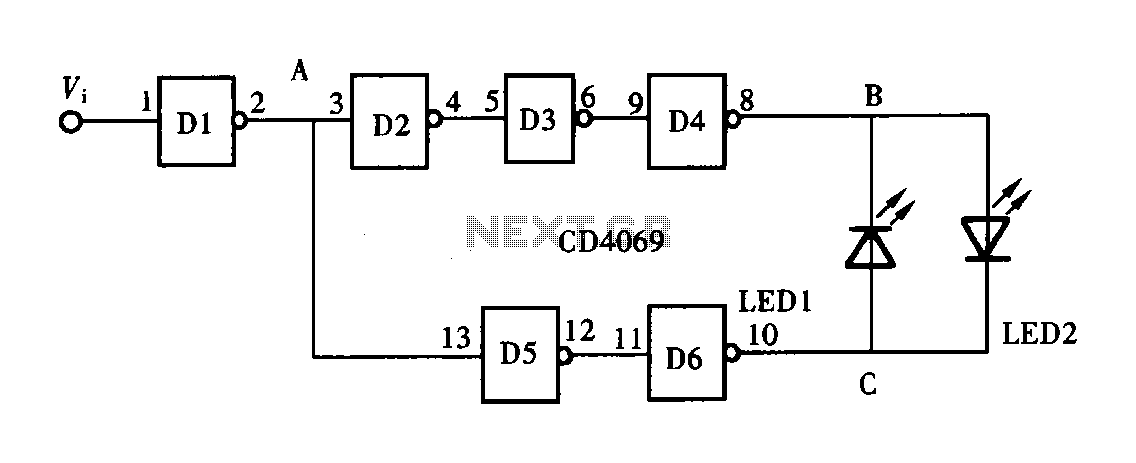
A logic pen, also known as a logic detection probe, is a commonly used tool for detecting the logic state at various points within digital circuits. The logic states in digital circuits are typically categorized into three types: a...
It may be necessary to use 10 diodes and various resistors, particularly when utilizing white LEDs. Refer to the Troubleshooting section in step 3 for more details. A sheet of 0.005-inch thick matte drafting film was purchased from a...
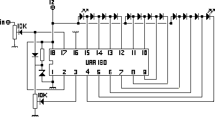
The NL3ASD schematic pages provide the schematics for a LED VU meter utilizing the UAA180 integrated circuit. The NL3ASD schematic pages feature a comprehensive design for a LED VU meter that employs the UAA180 IC, known for its audio signal...
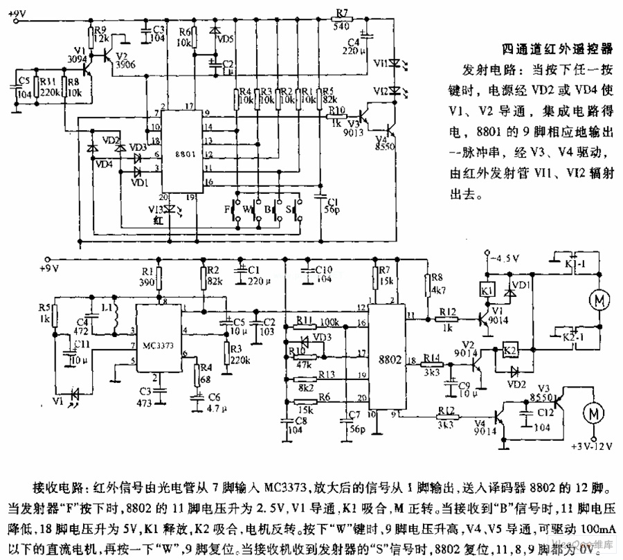
The receiving circuit involves an infrared signal being input to the MC3373 from pin 7 via a phototube. The amplified signal is output from pin 1 and sent to pin 12 of the decoder 8802. When the transmitter F...
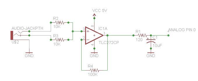
In a prior post titled "Timing is Everything," the application of PWM (Pulse Width Modulation) signals for controlling devices such as LEDs was discussed. This technique is particularly beneficial when working with digital devices, including microchips and microcontrollers, which...