
usb audio multiplexer
The circuit design incorporates several key components and configurations that enhance its functionality and efficiency. The isolation of the audio ground from the digital ground using the top copper layer as a shield is a critical feature that minimizes interference, ensuring high-quality audio output. The relay control circuit, including resistor R3 and capacitor C2, serves to optimize power consumption, which is essential for battery-operated or USB-powered devices where current draw is a consideration.
The choice of the ATtiny13A as the microcontroller is notable for its compact size and low pin count, making it suitable for simple applications while still allowing for the implementation of a software UART. The use of an external interrupt and timer for the software UART, although potentially over-engineered for this application, demonstrates a thorough approach to ensuring reliable serial communication. The calibration of the internal RC oscillator is a critical factor that requires attention, as it directly impacts the performance of the UART protocol.
In terms of flexibility, the ability to modify the functions of the FT232R's CBUS pins provides additional versatility, allowing the designer to adapt the circuit for various use cases. The design's adaptability extends to the choice of relays, enabling the use of alternative components without significant redesign, provided that the electrical specifications are adhered to. Overall, this schematic description outlines a well-considered approach to designing an audio multiplexer that balances performance, power efficiency, and flexibility, making it suitable for a range of applications.As you can see, the audio ground completely isolated from digital ground. And I`m using top copper layer as a shield for both, audio and digital ground. This helps to isolate audio part from picking up noise from digital circuitry and other EMI. Relay connected not straight to MCU pin, but it is connected through R3 and C2. It`s made for lowering relay power consumption from 28mA to about 12mA. I wrote about this trick in my article: Using Relays (Tips & Tricks). This might be helpful when this device is connected through usb-hub full of devices, when even ~15mA can make a difference. But it is not necessary implement this. Pin PB3 of MCU connected to CBUS3 pin of FT232R with 10k pull-up resistor, which can be used for power saving functions, or it can be used for providing clock to ATmega13A.
You can change functions of CBUS pins of FT232R using FT_Prog software which you can download from FTDI website At first I wanted to make single-sided board, but eventually I`ve end up with double-sided one. Because of that the USB connector stayed on the bottom of the board and audio connectors on the top. But if you want you can easily change that fact. If you can`t find the exact relay I`ve used in this design, you can use any DPDT (2 Form C) 5VDC signal relay which not exeeds ATtiny13 maximum pin current.
And for different relay you might need to change R3 and C2 values (if you don`t care about saving a couple of dozen of milliamps, just put jumper in there). For this simple task I was looking for cheap microcontoller(preferably from Atmel of Microchip) with minimal number of pins and with hardware UART.
But the smallest and cheapest thing I found was the PIC16F688T from Microchip. Well, I guess 14 pins is too much for this task, so I`ve ended up using ATtiny13A, which, btw I had in my junk box. I just decided to write software UART for this micro. To do that I`ve used AVR304 app-note from Atmel Half Duplex Interrupt Driven Software UART . I`ve used 8-bit timer and one external interrupt to do that, but for this simple task it`s actually is overkill.
It is possible to use only a small fraction of memory to implement software UART without using external interrupts and timers. Anyways, if you want you can still do that. The only issue I had with this device was ATtiny13 internal RC oscillator calibration. UART protocol is very sensitive to changes in oscillator frequency. ATtiny13 internal oscillator is calibrated under 3V and 25 degrees C, but in this Audio Multiplexer it`s powered straight from USB port 5V, and because of that it can even not work after you will flash the firmware.
You might need to tweak number of timer cycles in firmware (read comments in code, there`s only two values at the beginning of the program). To conquer that you might try to configure CBUS3 pin of FT232R as a clock source for ATtiny13, hoping that FT232R internal RC oscillator is more precise than ATtiny`s oscillator.
Or put external crystal for FT232R and still use CBUS3 as ATtiny13 clock source that would`ve been the ideal solution. I maybe will compare FT232R internal oscillator frequency stability against ATtiny13A internal oscillator.
Maybe. If you`ll try to do that before me, it would be interesting to know what the result is. 🔗 External reference
Related Circuits
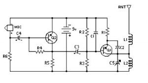
4 Stage FM Transmitter. This FM transmitter circuit utilizes four radio frequency stages, functioning as a VHF oscillator. It is available for wholesale through fmuser, including the CZE and CZH models of FM transmitters, which are suitable for OEM...
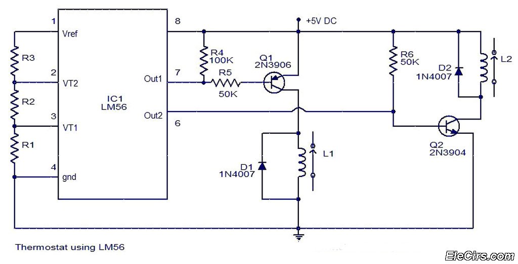
The LM56 Thermostat Project Circuit Diagram includes a schematic for the LM56 thermostat. The values of resistors R1, R2, and R3, which determine the required trip points VT1 and VT2, can be calculated using the following equations: VT1 =...
The circuit consists of a frequency modulated oscillator, an audio preamplifier with pre-emphasis to supply the frequency modulating signal, and a buffer amplifier to drive the antenna connector. Oscillator's frequency is determined by L1 resonating with the 10 pF...

This project involved the design of an audio amplifier that delivers substantial output power while maintaining a minimal parts count and high quality. The power amplifier section utilizes only three transistors along with a few resistors and capacitors arranged...
A program is needed to set the channels to their maximum level or to write the full scale to the Digital-to-Analog Converter (DAC). The MD schematics indicate that the audio signals are mixed with ratios of 0.0431 for the...

A simple audio watt meter circuit or an audio power or audio level meter circuit with diagram and schematics to measure amplifier audio output power in watts. The audio watt meter circuit is designed to measure the output power of...
Warning: include(partials/cookie-banner.php): Failed to open stream: Permission denied in /var/www/html/nextgr/view-circuit.php on line 713
Warning: include(): Failed opening 'partials/cookie-banner.php' for inclusion (include_path='.:/usr/share/php') in /var/www/html/nextgr/view-circuit.php on line 713