
FM Broadcast Audio Transmitter
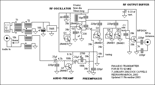
All of the transistors in the oscillator - Q1 through Q5, are 2N4401.
The purpose of the buffer is to minimize frequency shift as loading on the antenna is changed. It was specifically designed to reduce the signal amplitude to the antenna. Transmitters should not use any more power than is necessary to achieve the task at hand, and lightly coupling the RF into the buffer's base with a gimmick capacitor did the trick. The transistor is an MPSH34.
The audio preamp that drives the frequency modulation state is a single inverting transistor. The open-loop gain of Q7 is about 150 (mostly set by the voltage across the collector resistor) and the closed-loop gain of the stage is about 20 (set by the ratio of the 100k feedback resistor to the 4.7k input resistor). A pre-emphasis network is flat from about 3 Hz to 350 Hz, then the response increases at 6 dB/octave until it levels off around 3 kHz. This particular network was selected to make CDs sound good on the portable radio being used. It does not conform to either the British or American FM radio pre-emphasis curve.
The power supply is DC from a mains-powered power supply (a switching power supply is not recommended) and the voltage is regulated to +5V with an LM7805 T regulator.
Construction
The circuit should be built on a ground plane board, emphasizing the importance of layout. Components should be placed relative to one another as per their schematic representation to ensure proper functionality. The construction method employed is "dead bug" style, where components are mounted with legs up. Grounded components are soldered directly to the ground plane, providing structural integrity. Keeping leads short is advisable, particularly for circuits operating at high frequencies.
The inductor is constructed by winding 8 turns of #24 insulated solid copper wire around a 5 mm screwdriver. Using a conductor from a piece of category-5 quad twisted pair is recommended for ease of handling. The tuning range of the transmitter can be adjusted by modifying the number of turns on L1. A FM radio receiver can be used as a reference for tuning adjustments. The objective is to set the transmitter to oscillate around 90 MHz when the tuning knob is at its center position.
To adjust the coil, if the oscillator is audible when the tuning pot's wiper voltage exceeds 2.5 volts, the oscillator's range is too low, necessitating compression of the coil or the addition of a turn. Conversely, if the oscillator is heard below 2.5 volts, the coil should be stretched or a turn removed. If the frequency is excessively high, touching L1 can add capacitance to bring the frequency down. If too low, stretching the coil may increase the frequency range.
C1, the capacitor supplying the signal to the base of the output buffer transistor, is a gimmick capacitor. It is made by tightly twisting two wires together and cutting them to size, providing a small capacitor where precision is not critical. Gimmicks can also be used as tuning capacitors, although multiple iterations may be necessary to achieve the optimal length.The circuit consists of a frequency modulated oscillator, an audio preamplifier with pre emphasis to supply the frequency modulating signal, and a buffer amplifier to drive the antenna connector. Oscillator's frequency is determined by L1 resonating with the 10 pf capacitor and the total capacitance across it.
The collector-base capacitance of the transistors Q3, Q4, and Q5 is a function of their revers bias. This is basically a poor man's (or lazy man's) varactor. The voltage across Q3 is set by a voltage divider and is then modulated by an Ac coupled audio signal from the pre amp, causing the reverse bias to vary with the audio signal, which changes the resonant frequency of L1's circuit, causing the frequency of the oscillator to vary with the audio signal. The capacitance of Q4 and Q5 is adjusted by DC bias from the tuning adjustment potentiometer, and this capacitance sets the center frequency of the oscillator. All of the transistors in the oscillator -Q1 through Q5, are 2N4401. The purpose of the buffer is to minimize frequency shift as loading on the antenna is changed. It was specifically designed to reduce the signal amplitude to the antenna. Transmitters should not use any more power than is necessary to achieve the task at hand, and lightly coupling the RF into the buffer's base with a gimmick capacitor did the trick.
The transistor is an MPSH34. The audio pre amp that drives the frequency modulation state is a single inverting transistor. The open loop gain of Q7 is about 150 (mostly set by the voltage across the collector resistor) and the closed loop gain of the stage is about 20 (set by the ratio of the 100k feedback resistor to the 4.7k input resistor). A pre emphasis network is flat from about 3 Hz to 350 Hz, then the response increases at 6 db/octave until it levels off around 3 kHz.
This particular network was selected by me to make my CDs sound good on the portable radio I was using at the time. It doesn't conform to either the British or American FM radio preemphesis curve. Do I need to point out that the power supply is DC from a mains-powerd power supply (please don't use a switching power supply for this unless you are adventurous) and the voltage is regulated to +5V with an LM7805 T regulator.
Construction Build this on a ground plane board. Layout is important. If you place the parts relative to one-another in correspondence with their placement on the schematic, it should work pretty well. I built this one "dead bug" style, in which the components are mounted legs up. The grounded components are soldered directly to the ground plane, and its these components that hold everything together.
The resulting assembly can be fairly rugged if the leads are kept short, which is always a good idea when building circuits that operate at high frequencies. The inductor is made by winding 8 turns of #24 insulated solid copper wire on a 5 mm screwdriver. I used a conductor from a piece of category-5 quad twisted pair, left over from wiring the house with Ethernet and this seems to work well and to be easy to handle.
The tuning range of the transmitter is adjusted by stretching or compressing, or adding or removing a turn on L1. In your particular layout, you might even have to add or remove a turn from the coil. you can use and FM radio receiver as a reference for adjusting the turning range (see the note below about FM receivers).
Tune the receiver to a clear spot on the dial around 90 MHz. The idea is to adjust the coil so that the transmitter oscillates at this frequency when the tuning know is set to the center of its range. Before you can adjust the coil, you need to find out whether the oscillator is running at to high of a frequency or too low.
If you can hear the oscillator go by as you adjust the tuning knob,the hiss in the receiver will become noticeably less when the transmitter is tuned to the receive frequency, or you will hear thump if you tune through quickly, adjusting the coil will be fairly easy. If the oscillator is heard when the voltage on the wiper of the tuning pot is above 2.5 volts, the oscillator's range is too low, and this can be corrected by compressing the coil or adding a turn.
On the other hand, if the oscillator is heard when the voltage on the wiper of the tuning pot is below 2.5 volts, the oscillators' range is too low and this means that the coil needs to be stretched a little or have a turn removed. If the oscillator frequency is way too high, that is, too high for the tuning knob to bring the signal down to the receiver's frequency, you can help things out by touching your finger to L1 to add additional capacitance.
If the frequency is too low, you will need to try stretching the coil to try and raise the frequency range. C1, the capacitor that supplies the signal to the base of the output buffer transistor is a gimmick capacitor.
A gimmick is made by tightly twisting two pieces of wire together and cutting it to size. Its a nice way to make a small capacitor where the actual value isn't critical. I've also used gimmicks to use as tuning capacitors. Twist up a length of capacitor and clip it shorter and shorter until the circuit is tuned. The problem with that approach is that you may have to make a few of these in order to learn what the optimum length is. 🔗 External reference
Related Circuits
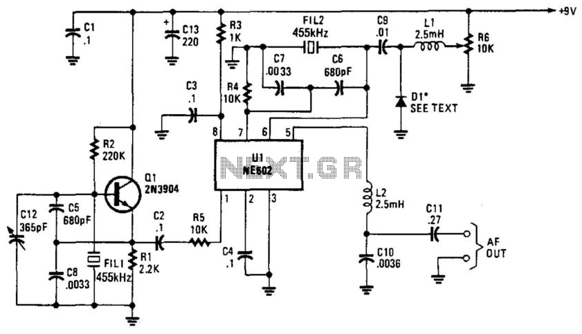
Q1 is a fixed oscillator operating at 455 kHz. U1 is a mixer with its own internal oscillator running at 45.5 kHz. FIL1 and FIL2 are Murata CSB455E filters or equivalent. D1 is a varactor diode (an IN4002 used...
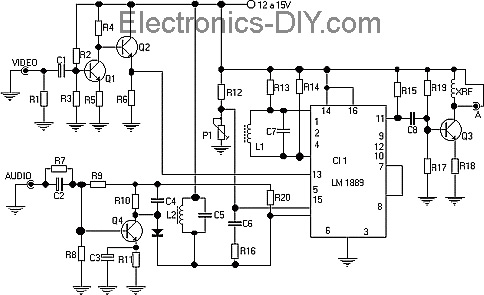
This TV transmitter transmits audio and video signals from camcorders, DVD players, VHS players, satellite systems, video games, etc., broadcasting them on a channel free from the VHF strip. These signals can be radiated using a common antenna and...
This document discusses the advantages and disadvantages of various power supply technologies, along with the design considerations necessary for selecting and evaluating a mains transformer. It covers the pros and cons of external supplies, inrush current control, RF emissions...
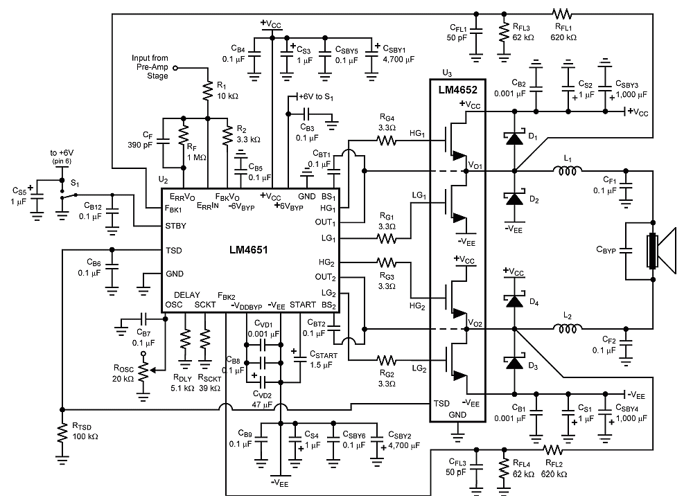
The combination of controller IC LM4651 and LM4652 Class D MOSFET power amplifier IC provides a high-efficiency solution suitable for powered speakers, subwoofers, and car amplifiers. The LM4651 is a fully integrated conventional pulse width modulator (PWM) driver, which...
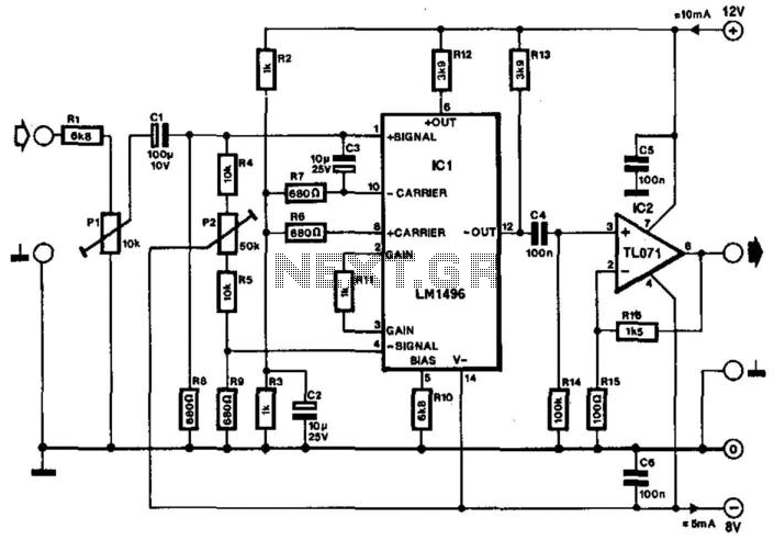
Often, the frequency of a signal must be doubled, and the modulator/demodulator chip LM1496 serves as an ideal basis for this application. From trigonometry, it is well known that 2sin(x)cos(x) = sin(2x) and sin^2(x) = 1 - cos^2(x). These...
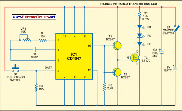
Most IR remotes function effectively within a range of 5 meters. Designing an IR transmitter for dependable operation over a longer distance, such as 10 meters, increases circuit complexity. To achieve this doubled range, the transmitted power must be...