
USB FM Transmitter Circuit
The USB FM transmitter circuit is designed for easy integration into various audio applications, providing a straightforward solution for wireless audio streaming. The use of the MAX2606 integrated circuit simplifies the design by minimizing the number of external components required, enhancing reliability and reducing assembly complexity. The incorporation of a common-mode choke is critical for maintaining signal integrity, especially in environments with potential RF interference.
The audio input stage, which utilizes resistors R1 and R2 for combining stereo signals, allows for flexibility in audio source compatibility. The volume control potentiometer P1 not only adjusts the output level but also influences the modulation characteristics of the transmitter, providing a unique approach to managing audio levels.
The PCB layout is optimized for size, making it suitable for portable applications, while the choice of SMD components ensures a compact form factor. The design's ability to operate on USB power or batteries adds to its versatility for various use cases, whether at home or on the go.
Overall, this USB FM transmitter represents an effective solution for users seeking to broadcast audio wirelessly, with considerations for performance, size, and ease of use. The design allows for customization and adjustments based on user preferences, making it a valuable addition to personal audio equipment.A simple USB FM transmitter that could be used to play audio files from an MP3 player or computer on a standard VHF FM radio by connecting it to an USB port. The circuit use no coils that have to be wound. This USB transmitter can be used to listen to your own music throughout your home. To keep the fm transmitter circuit simple as well as compact, it was decided to use a chip made by Maxim Integrated Products, the MAX2606. This IC from the MAX2605-MAX2609 series has been specifically designed for low-noise RF applications with a fixed frequency. The VCO (Voltage Controlled Oscillator) in this IC uses a Colpitts oscillator circuit. The variable-capacitance (varicap) diode and feedback capacitors for the tuning have also been integrated on this chip, so that you only need an external inductor to fix the central oscillator frequency.
It is possible to fine-tune the frequency by varying the voltage to the varicap. Not much is demanded of the inductor, a type with a relatively low Q factor (35 to 40) is sufficient according to Maxim. The supply voltage to the IC should be between 2. 7 and 5. 5 V, the current consumption is between 2 and 4 mA. With values like these it seemed a good idea to supply the circuit with power from a USB port. A common-mode choke is connected in series with the USB connections in order to avoid interference between the circuit and the PC supply.
There is not much else to the circuit. The stereo signal connected to K1 is combined via R1 and R2 and is then passed via volume control P1 to the Tune input of IC1, where it causes the carrier wave to be frequency modulated. Filter R6/C7 is used to restrict the bandwidth of the audio signal. The setting of the frequency (across the whole VHF FM broadcast band) is done with P2, which is connected to the 5 V supply voltage.
The PCB designed uses resistors and capacitors with 0805 SMD packaging. The size of the board is only 41. 2 x 17. 9 mm, which is practically dongle-sized. For the aerial an almost straight copper track has been placed at the edge of the board. In practice we achieved a range of about 6 metres (18 feet) with this fm transmitter usb. There is also room for a 5-way SIL header on the board. Here we find the inputs to the 3. 5 mm jack plug, the input to P1 and the supply voltage. The latter permits the circuit to be powered independently from the mains supply, via for example three AA batteries or a Lithium button cell. Inductor L1 in the prototype is a type made by Murata that has a fairly high Q factor: minimum 60 at 100 MHz.
Take care when you solder filter choke L2, since the connections on both sides are very close together. The supply voltage is connected to this, so make sure that you don`t short out the USB supply! Use a resistance meter to check that there is no short between the two supply connectors before connecting the circuit to a USB port on a computer or to the batteries.
P1 has the opposite effect to what you would expect (clockwise reduces the volume), because this made the board layout much easier. The deviation and audio bandwidth varies with the setting of P1. The maximum sensitivity of the audio input is fairly large. With P1 set to its maximum level, a stereo input of 10 mVrms is sufficient for the sound on the radio to remain clear.
This also depends on the setting of the VCO. With a higher tuning voltage the input signal may be almost twice as large (see VCO tuning curve in the data sheet). Above that level some audible distortion becomes apparent. If the attenuation can`t be easily set by P1, you can increase the values of R1 and R2 without any problems.
Measurements with an RF analyzer showed that the third harmonic had a strong presence in the transmitted spectrum (about 10 dB below the fundamental frequency). This should really have been much lower. With a low-impedance source connected to both inputs the bandwidth varies from 13. 1 kHz (P1 at maximum 🔗 External reference
Related Circuits
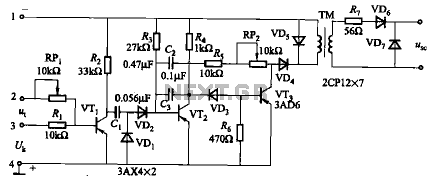
The circuit is designed for inductive loads, specifically within a thyristor power unit, such as a three-phase step-down DC motor speed control and other applications. It is capable of delivering sufficient output power to trigger a thyristor rated at...

This circuit was designed by Lazar Pancic from Yugoslavia. A typical PC sound card includes a microphone input, speaker output, and occasionally line inputs and outputs. The microphone input is specifically tailored for dynamic microphones with an impedance range...
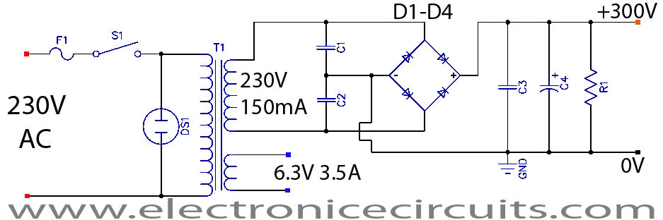
This project is a successful vacuum tube amplifier utilizing a 6V6GT output pentode configured in triode mode, producing approximately 4.5 watts of output power. The design features a single-ended audio amplifier with a resistive input network, a driver stage,...
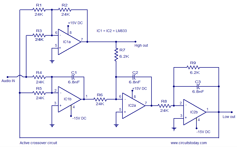
Active crossover circuit design, circuit diagram, schematic, DIY active crossover circuit, HiFi audio crossover, 2-way crossover circuit using LM833. The active crossover circuit is an essential component in high-fidelity audio systems, allowing for the separation of audio signals into different...
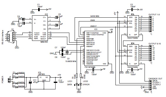
This basic PIC-based RS-232 serial interface can control up to 120 digital TTL outputs. The described circuit utilizes a PIC microcontroller to facilitate communication via the RS-232 protocol, which is a standard for serial communication. The interface primarily serves to...

This circuit design for a low current relay is intended for use in battery-operated electronic devices, with an operating current in microamperes (µA). It utilizes a bistable relay and additional components to enable the relay to function similarly to...