
low current relay circuit

The low current relay circuit is particularly advantageous for battery-powered applications due to its minimal power consumption. The use of a bistable relay allows the circuit to maintain its state without continuous power, significantly extending battery life. The charging mechanism involving capacitor C1 and diode D1 ensures a rapid response time when the circuit is powered on, while the careful arrangement of transistors T1 and T2 facilitates a smooth transition between states when power is removed.
In practical implementation, the selection of components such as the relay and capacitors should be made considering the specific application requirements, including the expected load and switching frequency. The relay must be capable of handling the load current while remaining within the specified voltage range to prevent damage or unreliable operation. The use of low-value resistors in series with the relay coil may be considered to fine-tune the operating current and ensure compatibility with the power supply voltage.
Overall, this circuit design exemplifies an efficient method for controlling a relay with minimal power consumption, making it suitable for various low-power electronic applications where battery life is a critical factor.This is a design circuit for low current relay circuit is designed to be used in battery operated electronic devices. Its operating current is in micro amperes ( µA). This is done by using a bistable relay and adding some components to force the relay to behave like a mono stable relay.
A bistable relay stays at its last state when the power is tu rned off but consume at least 50mA trigger current. A mono stable relay switches back to its original state when the power is turned off. Here`s the figure of the circuit; How this circuit can operate When the power is turned ON, the C1 charges via D1 and the relay coil and this current activates the relay. D1 ensures that the base of T1 is always more positive than its emitter and because of this T1 and T2 are always blocked.
Once the power is turned OFF, the emitter of T1 is coupled to the charge voltage at the positive pole of C1. Its base and the relay coil on the other hand are coupled to the negative pole of C1 and now T1 and T2 conduct, C1 can discharge through T2 and relay.
The current flows to the relay coil but in reverse order so is activated to its other state. It has the advantage of consuming little current, around 150 µA. For a reliable operation, select the relay`s operating voltage as 2/3 to 3/4 of the main power supply. For example is using a 12V power supply select a 9V relay. 🔗 External reference
Related Circuits
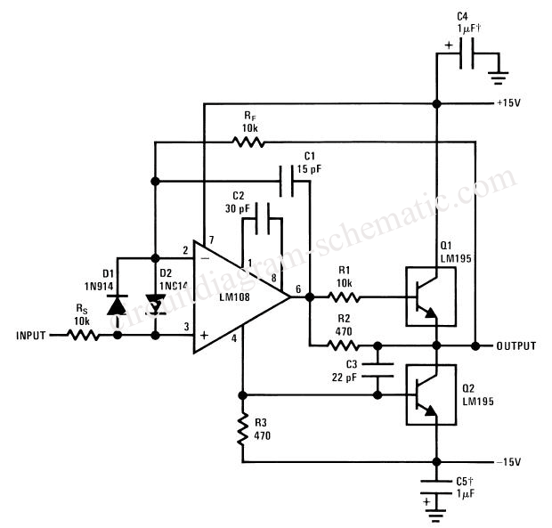
A simple power operational amplifier circuit designed for operation up to 300 Hz. One variant of this circuit presents challenges in protecting the flow regulator due to its fixed nature, rendering standard protections ineffective. The circuit is intended to...
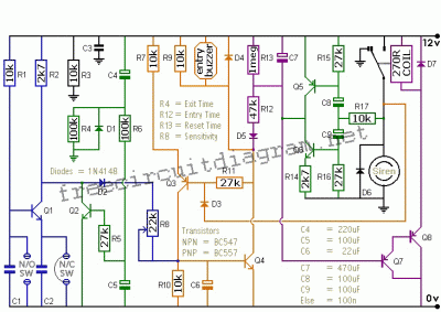
This is a single alarm circuit. The circuit includes automatic exit and entry delays, a timed bell cut-off, and a system reset. It has provisions for normally open and normally closed inputs. The single alarm circuit is designed to provide...
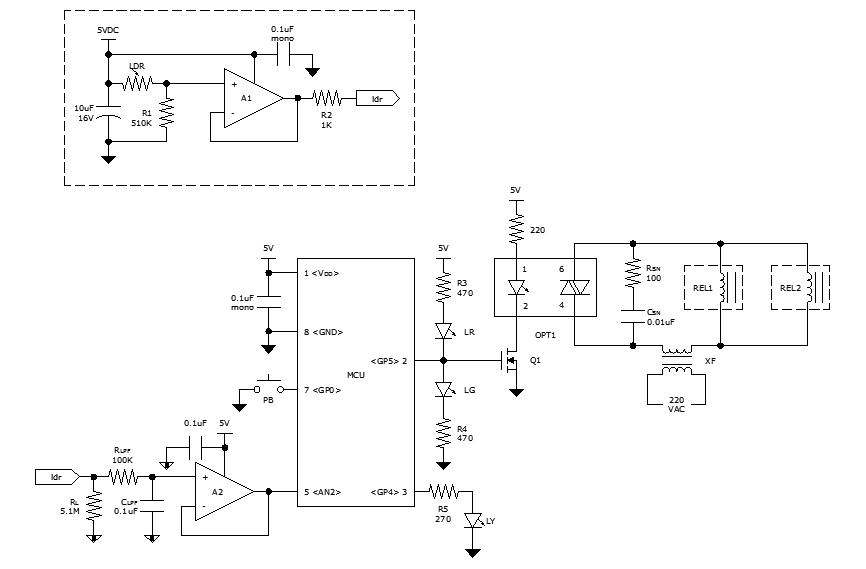
While discussing an all-linear automatic night light circuit, it was mentioned that an MCU-based Automatic Night Light Controller (ANLC) was being tested. The firmware has been tweaked since then. Recently, the sensor was installed outdoors and connected to control...
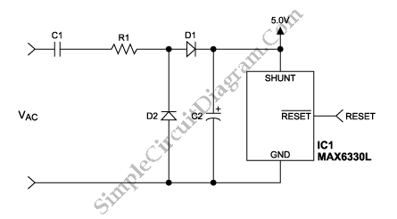
Applying the filtered and rectified AC input to a high-input-voltage linear regulator is the simplest way to produce a low current level from an AC source. The process of converting an AC source to a low current level using a...
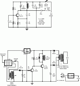
This circuit is a wireless car alarm system constructed using two modules: a transmitter module and a receiver module. It operates on FM radio waves and is suitable for vehicles with a power supply of 6-12VDC. A voltage stabilizer...
This circuit is a single transistor flyback (Joule Thief) circuit that features a third coil. With it, flash duration and brightness are significantly enhanced. The single transistor flyback circuit, commonly known as a Joule Thief, is designed to efficiently convert...