
Light Flashing Car 12 Volt using LM3900

The 12V flasher relay circuit is a crucial component in automotive lighting systems, primarily used for turn signals and hazard lights. The circuit typically consists of a 12V power supply, a flasher relay, and the associated lighting elements, such as incandescent or LED bulbs.
The flasher relay is designed to intermittently connect and disconnect the power supply to the lights, creating a blinking effect. It operates on the principle of thermal or electronic switching, depending on the type of relay used. In a mechanical flasher relay, a bimetallic strip heats up and bends to break the circuit, while in an electronic relay, a transistor or a similar component is used to control the timing of the on/off cycle.
To construct a basic 12V flasher relay circuit, the following components are typically required:
1. A 12V power source, such as a car battery.
2. A flasher relay rated for 12V operation.
3. Two light bulbs (incandescent or LED) to serve as indicators.
4. Connecting wires and a fuse for safety.
The circuit is assembled by connecting the power supply to the input terminal of the flasher relay. The output terminals of the relay are then connected to the light bulbs. A fuse should be placed in line with the power supply to prevent overcurrent situations.
When the circuit is activated, the flasher relay will begin its on/off cycle, causing the connected bulbs to blink. The timing of the blinking can be adjusted by changing the capacitor and resistor values in the circuit, if applicable, in the case of an electronic relay.
This circuit is widely used in automotive applications due to its simplicity and effectiveness in alerting other drivers of the vehicle's intentions, thereby enhancing road safety.If you have evered to use Flasher Relay 12V systematic usual mechanical , for general automobile. Today we try to come to build Circuit Flasher Relay 12V , use. 🔗 External reference
Related Circuits
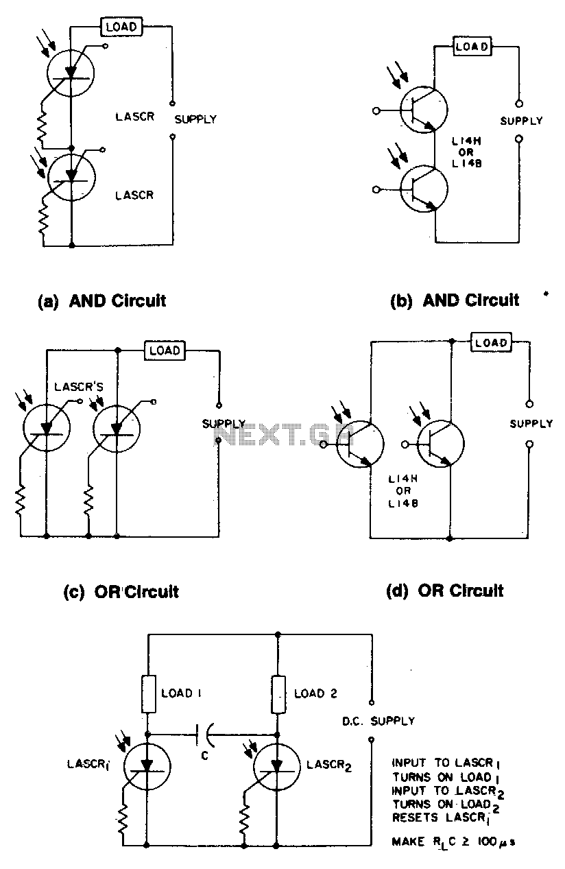
These circuits illustrate some of the common logic functions that can be implemented. The provided circuits serve as examples of fundamental logic functions utilized in digital electronics. Logic functions are the building blocks of digital systems, enabling the execution of...

This circuit is designed for line detection in a robot project. A proper match between the transmitter and the detector is crucial for optimal operation, particularly when the hole is large. The robot is equipped with a simple system...
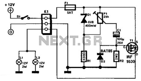
It is assumed that most readers are considerate drivers who do not activate their rear fog lights when closely followed by other vehicles. Following drivers may mistakenly think that the vehicle is braking, leading them to react by applying...
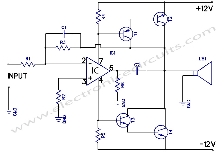
12W Amplifier Circuit Using 741 Op Amp. A 12-watt audio amplifier operates on a dual symmetrical supply of ± 12 volts. The 741 provides the... The 12W amplifier circuit utilizing the 741 operational amplifier is designed to deliver audio amplification...
The car parking sensor circuit utilizes a photodiode as the distance sensor. It measures the distance between adjacent sensors. The car parking sensor circuit employs photodiodes to detect the proximity of obstacles, enhancing parking safety and convenience. Photodiodes are semiconductor...

A simple circuit diagram illustrates a schematic for a remote control system, which consists of two parts: the transmitter and the receiver. The transmitter circuit is controlled by an NE555 integrated circuit (IC) and operates by detecting the emitted...