
Using Motor Bridges
The L298 motor driver IC is a versatile component widely utilized in robotic applications for controlling DC motors and stepper motors. Its ability to manage dual motors simultaneously makes it suitable for various robotic platforms, from simple hobby projects to more complex autonomous systems. The H-bridge configuration allows for bidirectional control, enabling motors to rotate in both clockwise and counterclockwise directions, which is essential for applications requiring precise movement control.
In practical implementations, the L298 can be interfaced with microcontrollers such as Arduino or Raspberry Pi, allowing for programmable control of motor speed and direction. The PWM capability of the L298 facilitates speed modulation, which is crucial for applications requiring variable speed control. By adjusting the duty cycle of the PWM signal applied to the Enable pins, users can achieve fine control over the motor's speed, enhancing the robot's operational flexibility.
When designing a circuit utilizing the L298, careful attention must be paid to the power supply requirements. The motor supply voltage should be selected based on the motor specifications, ensuring that it falls within the 7V to 46V range supported by the L298. Additionally, the 5V supply for the logic circuitry must be stable to ensure reliable operation of the control signals.
Thermal management is another critical aspect when using the L298. As it can generate significant heat during operation, particularly at higher currents, proper heat sinking is essential to prevent thermal shutdown. Users should consider the thermal characteristics of their specific application and design the heat dissipation system accordingly.
Overall, the L298 motor driver IC remains a popular choice for robotics enthusiasts and engineers alike due to its robust performance, ease of use, and extensive community support, making it a reliable solution for motor control in various robotic applications.Bridges allow your robot to control high current motors. They literally "bridge" between the low-current logic circuitry of your robot`s brain to the high current demanded from the motors. Many, but not all, use the common "H" arrangement of control circuitry (usually power transistors) to provide on/off and directional controls to the motors - h
ence the oft-cited name H-bridge. Though often considered "old school, " motor bridges using relays solve a number of problems, and easily provide for handling motors demanding many amps of current. Especially when purchased surplus, relays offer a cost-effective means to control your robot`s motors.
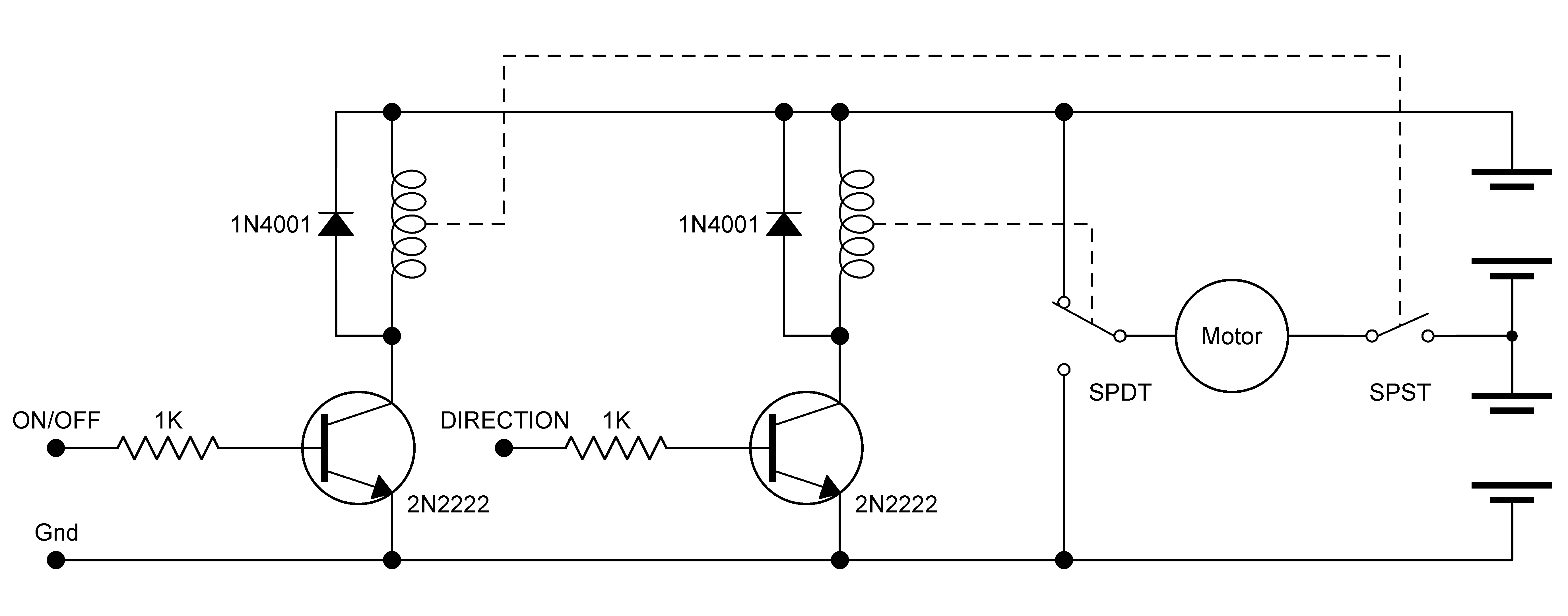
The following two circuits were contributed by robo-maestro Russell Cameron. Circuit 1 is a hybrid solution using a DPDT relay for controlling direction, and a power transistor for on/off control. The transistor can also be driven in low-frequency PWM (pulse width modulation) mode for controlling motor speed.
Circuit 2 is a half-bridge using a SPST and SPDT relay and transistor-controlled logic to manage on/off and direction. The bridge requires a split supply (two sets of batteries), and is well-suited for use when driving those small toy motors that are meant for 3V operation.
(Like all split-supply drivers, one set of batteries may deplete faster than the other, depending on the driving habits of your `bot. ) A very popular and reasonably priced all-in-one H-bridge motor control IC is the L298. It can control two motors, not just one. It can handle 2 amps per motor, though to get the maximum current be sure to add a heat sink. The L298 has a large cooling flange with a hole in it, making it easy to attach a homebrew metal heat sink to it.
If there`s a downside to the L298 it`s that it comes in a special Multiwatt 15 package, with 15 offset pins that don`t match the standard 0. 100" spacing of breadboards. But with care, the pins can be rebent as needed. Or you may prefer to simply get a breakout board for the L298, which is a small circuit board with holes drilled in it to accept the chip.
You then plug the breakout board into your breadboard. Problem solved. The schematic below shows a basic connection diagram for controlling two motors using the L298 motor bridge IC. There are three input pins for each motor: Input1, Input2, and Enable1 controls Motor1. Input3, Input4, and Enable2 controls Motor2. The L298 uses two different supply voltages. The voltage on pin 9 powers the chip itself and should be 5 volts. The voltage on pin 4 supplies the motors, and it can be up to 46 volts. The L298 has two additional inputs for sensing current on either motor. I won`t be demonstrating the current sense inputs here, but know they are available should you wish to experiment with them.
The L298 datasheet discusses how to use these inputs. Let`s look at how to control just one of the motors, Motor1. In order to activate the motor, the Enable1 line must be HIGH. You then control the motor and its direction by applying a LOW or HIGH signal to the Input1 and Input2 lines, as shown in this table. The L298 does not have built-in protection diodes, so you`ll need to add those. The datasheet for the L298 specifies fast recovery 1-amp diodes; an inexpensive selection is the 1N4933, available from most online electronic parts outlets.
The chip needs several other external parts for proper operation. Because of the added complexity of using the L298, frankly, most folks opt to get a fully integrated module based on the chip. Most of these are in kit form, so soldering is required, but they`re much easier (and often cheaper) to use than collecting and assembling all the parts yourself.
As noted above, the L298 is one of the more popular bridge modules to use on fully-developed commercial motor control boards. For example, the Dual H-Bridge board, from Seeedstudio, contains the L298 bridge on a heat sink, flyback diodes, screw terminals, indicat
🔗 External reference
Related Circuits
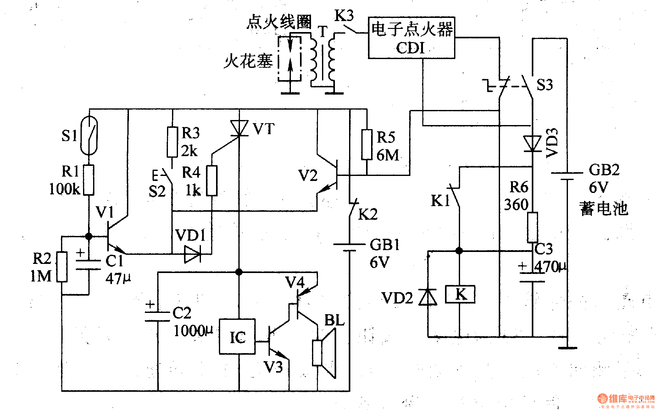
The multi-function motorcycle anti-theft alarm discussed in this article is suitable for anti-theft applications for all two-wheel motorcycles. The motorcycle anti-theft alarm circuit consists of a mobile delay alarm circuit, an ignition switch ground wire break alarm circuit, and...
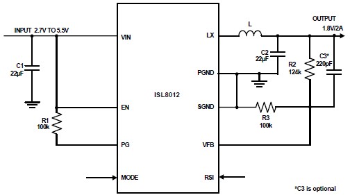
The ISL8012 is a high-efficiency, monolithic, synchronous step-down DC-DC converter that can be designed into a simple electronic project. It supports a maximum continuous output current of up to 2A from an input supply range of 2.7V to 5.5V....
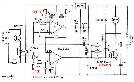
Like most other ESCs, this one is built up using N-channel Power MOSFETs because of their good characteristics (low DS resistance). Since this ESC has no reverse, it is not meant to be used in R/C cars or boats...
This circuit can be utilized to delay other appliances connected to the output of the relay. It operates to prevent equipment damage. This circuit is designed to provide a delay mechanism for appliances that are connected to a relay output....
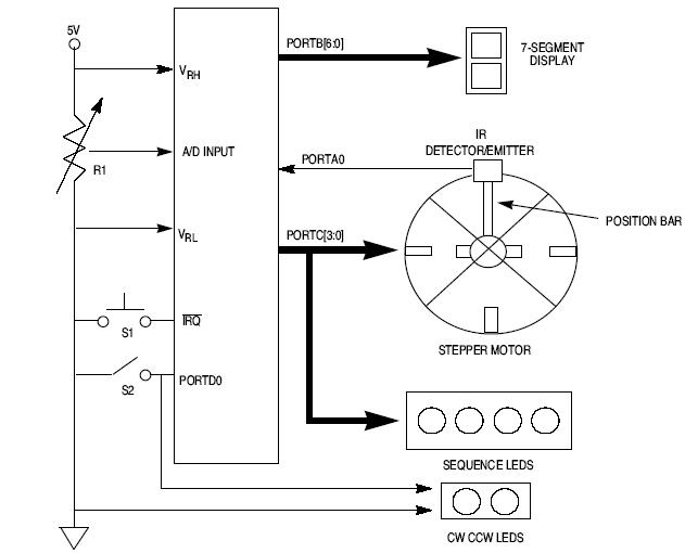
This article explains how to design a stepper motor system using an 8-bit Freescale microcontroller - MC68HC11E9. The design of a stepper motor system utilizing the 8-bit Freescale microcontroller MC68HC11E9 involves several key components and considerations to ensure effective control...
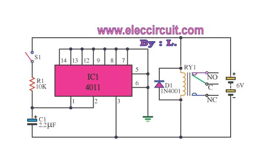
Here, S1 and S2 are normally open, push to close, press button switches. The diodes can be red or green and are there only to indicate direction. You may need to alter the TIP31 transistors depending on the motor...
Warning: include(partials/cookie-banner.php): Failed to open stream: Permission denied in /var/www/html/nextgr/view-circuit.php on line 713
Warning: include(): Failed opening 'partials/cookie-banner.php' for inclusion (include_path='.:/usr/share/php') in /var/www/html/nextgr/view-circuit.php on line 713