
Protection Surge with Delay the relay using ic 4011

This circuit is designed to provide a delay mechanism for appliances that are connected to a relay output. The primary function of the circuit is to ensure that connected devices do not receive power immediately when the relay is activated, thereby reducing the risk of damage due to sudden power surges or inrush currents.
The circuit typically consists of a relay, a timing component (such as a capacitor and resistor), and the connected load. When the relay is energized, the timing component begins to charge, creating a delay before the relay output is engaged. This delay can be adjusted by varying the values of the resistor and capacitor, allowing for flexibility based on the requirements of the connected appliances.
In operation, once the relay is activated, the timing circuit starts its countdown. After the predetermined delay, the relay contacts close, supplying power to the connected appliances. This delay is crucial for devices sensitive to power fluctuations, such as motors, compressors, or electronic equipment, ensuring that they are powered on in a controlled manner.
The circuit may also include additional features such as an indicator LED to show when the relay is in the delay phase or when it is activated. Protection diodes may be incorporated to safeguard the circuit from back EMF generated by inductive loads.
Careful consideration should be given to the relay specifications, including the voltage and current ratings, to ensure compatibility with the appliances being controlled. Additionally, the timing components should be selected based on the desired delay duration, balancing responsiveness with the need for protection against electrical stress.This circuit can be used to delay other appliances connected to the output of the relay. After working set To prevent equipment damage from. 🔗 External reference
Related Circuits
Port 1 of the controller (AT89C4051) is utilized as the data lines for the LCD (from pin 7 to pin 14 of the LCD). A 16 x 2 line LCD display is employed. The first line displays "DAY" and...
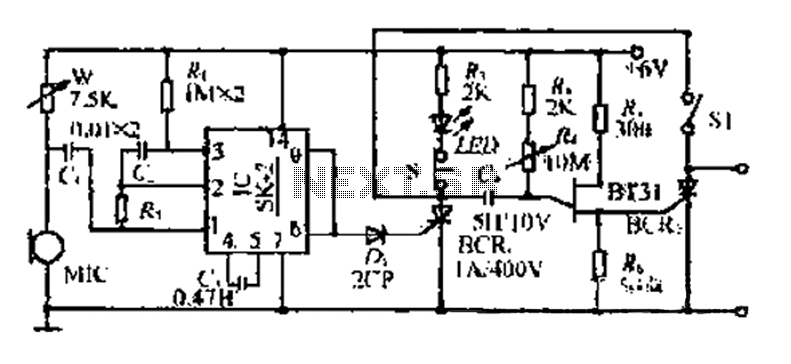
The circuit includes a microphone (MIC) housed in a cylindrical body that captures sound when an object makes contact. The audio signal is coupled to an integrated circuit (IC) for amplification. The output from the IC, at pins 6...
This is a short-range light barrier designed for use as an intruder alarm in doorposts and similar applications. The 555 timer in the transmitter oscillates at approximately 4.5 kHz. The short-range light barrier operates by utilizing a transmitter and a...
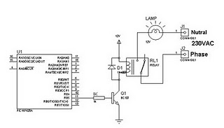
A relay can be controlled using a PIC microcontroller. The circuit illustrates how to control a single relay with the PIC 16F628. When the RB5 port of the PIC is set to high, the relay will activate. This circuit...
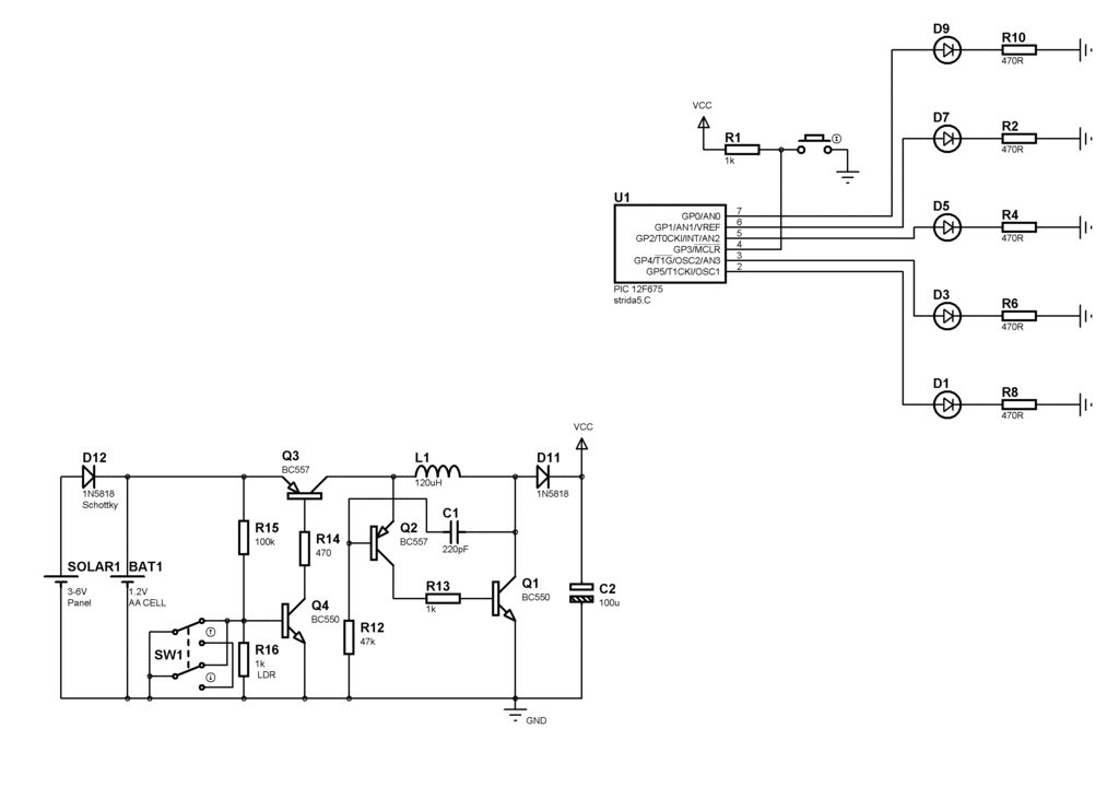
LED message system on a Strida folding bicycle wheel. After acquiring the Strida folding bicycle, one of the initial tasks was to explore instructions. The LED message system integrated into the wheel of a Strida folding bicycle serves as an...
This circuit diagram illustrates a triangular wave generating circuit utilizing a pair of operational amplifiers (Op-Amps). The LM741 Op-Amp is recommended for this application. The first Op-Amp, located on the left, functions as a comparator, while the second Op-Amp...