
using programming pods at the in circuit test stage
The described circuit utilizes a dual programming pod setup, specifically the P&E Micro Cyclone Pro, which is designed for ease of use in a manufacturing environment. The integration of multiplexers allows for simultaneous programming of multiple boards, enhancing efficiency. The multiplexers are controlled by an in-circuit test program, which facilitates automation and reduces the need for manual intervention by operators.
The design includes control lines that connect the START button and LED indicators (SUCCESS and ERROR) directly to the ICT machine. This connection allows the ICT program to execute commands and monitor the programming process in real-time. The inclusion of the USB connectors in the test fixture provides a straightforward method for firmware updates, ensuring that the programming pods can be easily maintained and kept up-to-date with the latest software versions.
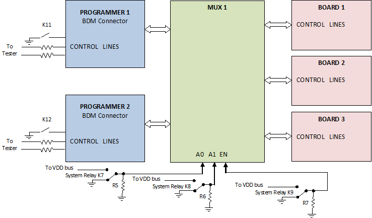
The overall architecture of this programming solution is aimed at minimizing downtime and maximizing throughput during the manufacturing process. By automating the programming sequence and integrating user-friendly interfaces, the system ensures reliable performance and simplifies the workflow for test engineers. The use of multiplexers not only addresses the challenges posed by panelized boards but also optimizes resource usage by allowing multiple boards to be programmed concurrently. This design exemplifies modern practices in electronic manufacturing and testing, highlighting the importance of automation and efficiency in the production of electronic devices.Nowadays using programming pods are commonly accepted and widely used in manufacturing, especially when a new product is introduced and the firmware is in the early development stages. After the completion of all visual and structure tests, the board is ready for full functional test. The in-circuit test station is the best point for programming a n electronic board for the following reasons: In a recent project, a customer asked to program a panelized board. Each board has two different programmable devices. Our approach was to use two programming pods (P&E Micro Cyclone Pro programming adapter) with multiplexers.
This project presented all four of the difficulties listed above. In order to overcome the panelized board issue, we decided to use two multiplexer boards which were being controlled through the in-circuit test program. Since there were six boards in each panel, each multiplexer was responsible for programming three boards.
Cyclone Pro programmers are very easy to use. As soon as the firmware is loaded, the user only needs to press the START button and monitor SUCCESS and ERROR LEDs. In order to automate the process, we decided to wire the above mentioned control lines (START button, SUCCESS and ERROR LEDs) to the ICT machine, so controlling the process would be through the ICT program and the operator will have no intervention.
After sending START command, the test program monitors two LEDs for the result. If SUCCESS LED turns on, the test program will send a Programming PASS message to the screen, otherwise the result is a fail and the screen will show Programming FAIL . In order to be able to upload the latest firmware into the programming pods, the test fixture incorporated 2 USB connectors, each of which was connected to one of the programming pods.
This allows a test engineer to quickly and easily upload a newly released firmware through the USB bus to the pods. 🔗 External reference
Related Circuits
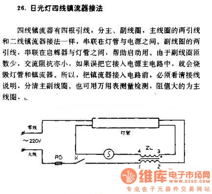
The four-wire ballast connection of a fluorescent lamp consists of four lead wires, which include main and auxiliary coils. The connection of the two lead wires in the main coil is similar to that of a second-line ballast; both...
This circuit is a 6-zone alarm system designed for independent operation, suitable for small office or home environments. It can be adapted to utilize a combination lock or keypad for setting and resetting the alarm. All zones, Z1 to...
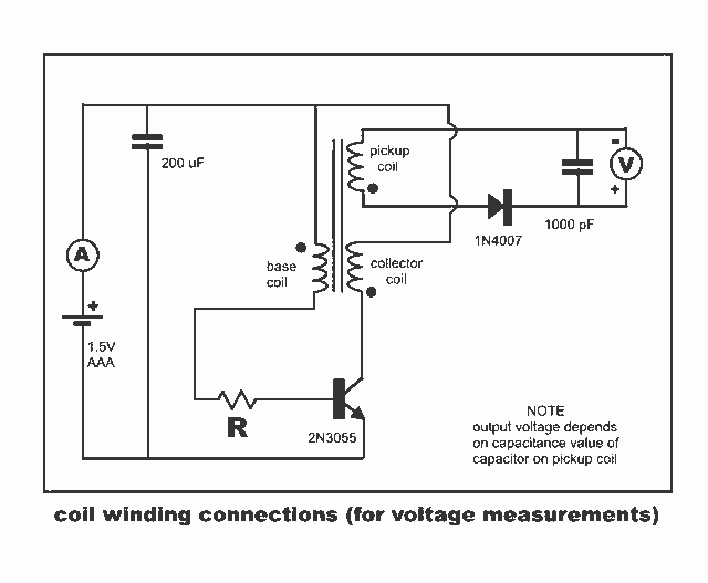
New Jewel Thief "Resonate LCR Circuit" with significantly reduced energy consumption. Measurements of voltage and current for the Joule thief. The Jewel Thief circuit, particularly the "Resonate LCR Circuit," is an innovative low-power design that enhances energy efficiency while maintaining...

This voltage regulator and current limiter combination can be constructed using two 7805 regulators as illustrated. Resistors R1, R2, and R3 should be chosen to achieve a 5-V drop at the maximum allowable current limit. Switch S1 selects one...
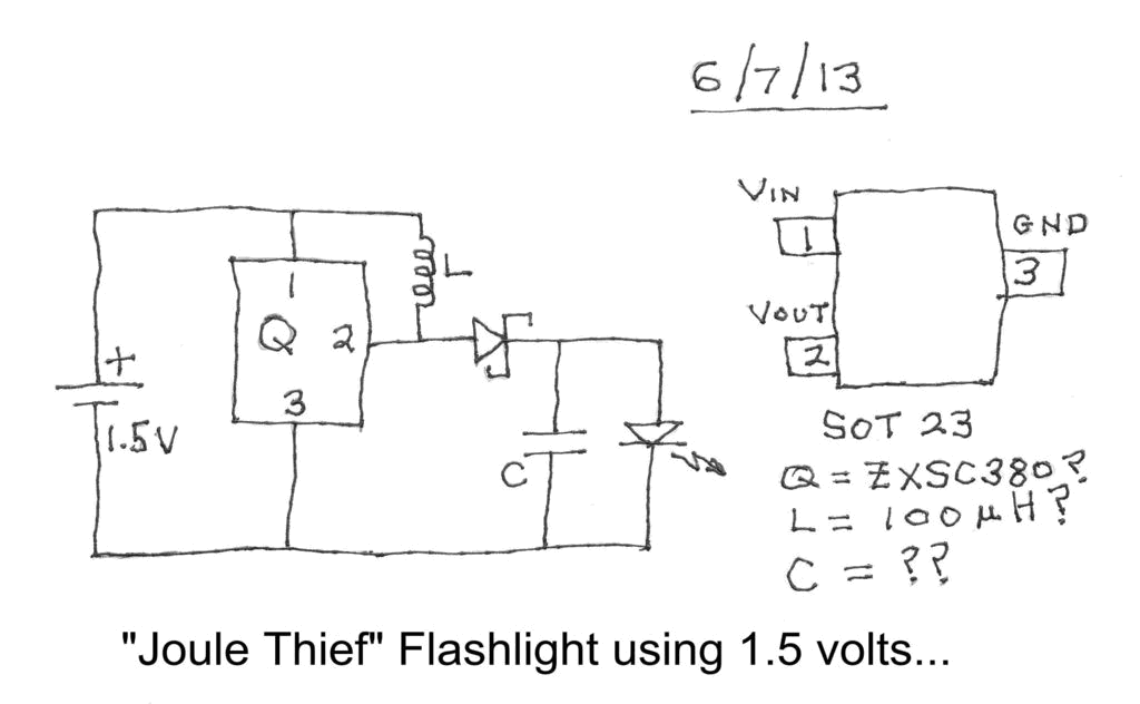
Investigating a Paradox: Recently, an energy-saving LED flashlight was observed for sale that utilized only one 1.5-volt battery. Upon purchasing this light and disassembling it, the expectation was to find a battery, bulb, switch, and a circuit board designed...
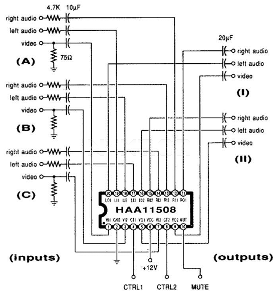
This channel selector selects video and stereo audio from any one of three different sources. The circuit should be constructed on a PC board with plenty of ground plane to minimize noise. The channel selector circuit is designed to facilitate...