
Using TX05C new infrared burglar alarm circuit diagram
The circuit operates effectively by combining infrared technology with a reliable alarm mechanism. The TX05C module serves as the core detection component, ensuring that any interruption in the infrared beam is detected promptly. The power supply circuit is crucial for maintaining stable operation, utilizing a transformer to step down the voltage and rectifier diodes to convert AC to DC. The three-terminal regulator ensures that the output voltage remains consistent, which is vital for the performance of the infrared transmitter and receiver modules.
The infrared transmitter (IC1) is designed to emit a modulated signal that can be recognized by the receiver (IC2). This modulation helps to differentiate between the alarm signal and potential noise, ensuring that only genuine interruptions trigger the alarm. The integration of a one-shot circuit (IC3) allows for a timed response to the alarm condition, providing a delay before the system resets. This feature prevents false alarms caused by brief interruptions, such as small animals or environmental factors.
The alarm speaker (BL) is selected for its loud output, ensuring that the alert is noticeable in the vicinity of the monitored area. The circuit's design allows for flexibility in installation, making it suitable for various applications beyond just doors and windows, including outdoor fences and indoor spaces requiring monitoring. Overall, the combination of infrared technology, integrated circuits, and a robust alarm system creates a reliable security solution for diverse environments. But here is a new type of infrared using TX05C radio sensor module made of doors and windows burglar alarm. Because it is not visible to the human eye utilizing infrared, wirel ess surveillance composition region, and therefore have a strong security and reliability, as long as someone enters the surveillance area, the body is bound to block the infrared beam, then the circuit will emit a loud alarm sound, to call attention to the duty officer. This circuit except for the windows and doors burglar alarm, but also can be used for walls, fences and other occasions need to be monitored.
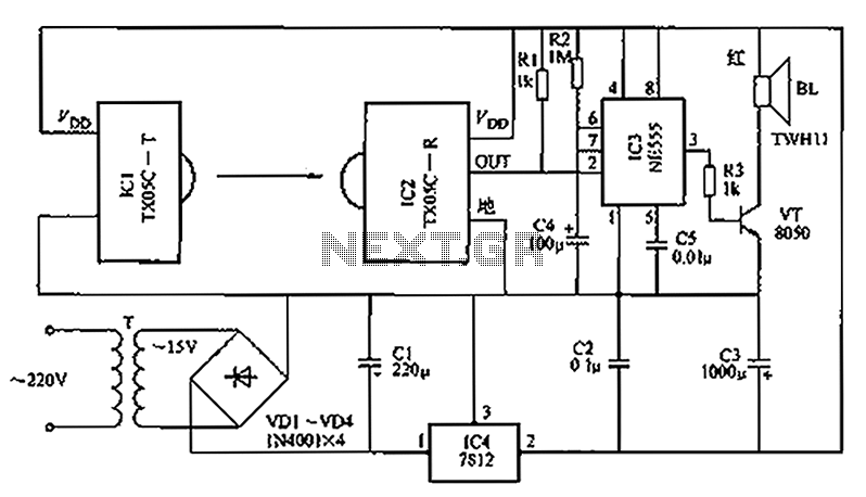
Infrared monitoring burglar alarm circuit diagram shown below, when the base integrated circuit, alarm speakers and power supply circuit of several parts of its circuit mainly by the infrared transmitter and receiver modules. Power circuit from the transformer T, rectifier diodes, three-terminal regulator IC4 hub and other parts, stable output voltage of 12V DC power supply of the entire circuit.
ICl infrared transmitter module, the internal power management devices, passwords integrated circuits, infrared modulation circuit and the power of infrared emitting diodes and other components, after power module in front of the lens aperture that is emitted outside via the integrated password modulated infrared. IC2 is supporting the infrared receiver module. When no one entered the monitoring area, IC2 receives infrared output terminal OUT module inside the transistor is turned off IC1 emitted is high, then the one-shot circuit from when base integrated circuit IC3 composition in the reset state, 3 feet without output, alarm loudspeaker BL silent.
If a person enters the monitored area, it will block the infrared radiation emitted by IC1, IC2 long once did not receive IR commands, OUT-side transistor is turned on inside that trigger Pin 2 of IC3 is triggered by the low, one-shot flip Now into the set state, 3 feet high output, VT conduction, BL electrical work, it will send a loud alarm sounds. In this case 12V positive supply to charge C4 through R2, after about 2min, value end level rises to 6 feet 2 encoding/3, IC3 reset, 3 pin output low, the circuit returns to the original stationary state.
Related Circuits

The integrated circuit (IC) is a multistandard vision and sound intermediate frequency (IF) phase-locked loop (PLL) demodulator that operates without the need for alignment. It supports multiple television standards, including PAL, SECAM, and NTSC, and is capable of handling...

Efforts were made to minimize the number of wire jumpers on this board, but space constraints arose due to the integration of the microcontroller and motor driver on a single board. The design would have been cleaner without the...
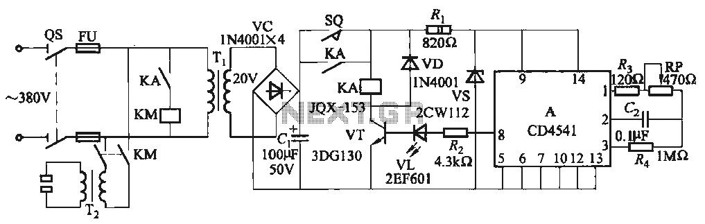
One Foot Spot Welder circuit. The circuit utilizes the IC CD4541 to provide precise delay characteristics, enabling the electrical time constant necessary for effective welding. This ensures consistent welding quality across identical weldments. For varying weldments, the electrical locator...
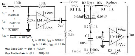
This topic continues from the more general Passive Tone Control circuit, which begins using only passive filters. This circuit follows the previous design, although the component values are different and in an alternate configuration. An audio tone control combines...
A circuit diagram for an animal repeller is provided. The circuit has been developed but is not functioning as intended. Assistance is requested for troubleshooting. The animal repeller circuit typically employs ultrasonic sound waves to deter animals from specific areas....
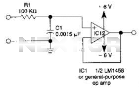
This simple filter utilizes an RC section as the filter element, incorporating a voltage follower to manage other frequencies. The -3 dB point is calculated as 1/(6.28 * RXCV), resulting in a response that drops 6 dB per octave...