
Active Audio Tone Control Circuit Design
The audio tone control circuit described employs an operational amplifier (Op Amp) in conjunction with passive filtering components to facilitate adjustments to the bass and treble frequencies of an audio signal. The configuration allows for a versatile approach to audio processing, where the Op Amp serves as a buffer and amplifier, enhancing the signal integrity while providing the necessary gain.
The inverting amplifier configuration of the Op Amp effectively isolates the input signal from the tone control circuitry, ensuring that the audio signal remains stable and unaffected by variations in the load or subsequent stages of the audio chain. The use of capacitors for DC blocking is critical in audio applications to prevent low-frequency DC offsets from interfering with the audio signal, which could lead to distortion or speaker damage.
The passive filter section is crucial for shaping the frequency response of the audio signal. The bass control section, implemented as a low-pass filter, allows frequencies below a specified cutoff to pass while attenuating higher frequencies. Conversely, the treble control section, designed as a high-pass filter, permits higher frequencies to pass while attenuating lower frequencies. The adjustable 3dB points for both the bass and treble sections provide flexibility, allowing users to tailor the audio output to their preferences.
The choice of the LM149 Op Amp, a quad package, offers efficiency in design, as multiple amplifiers can be utilized in a single package, reducing the overall component count and simplifying the PCB layout. The LM149's compatibility with other Op Amps in the LM148/LM149 series allows for easy substitutions, making it a popular choice among designers for various audio applications.
Overall, this circuit exemplifies a practical approach to audio tone control, combining the benefits of active amplification with passive filtering to achieve a customizable audio experience. The design can be adapted to suit different audio applications by altering component values, thus providing a robust solution for enhancing audio quality in various electronic devices.This topic continues from the more general Passive Tone Control circuit, which begins using only passive filters. This circuit follows the previous design, although the component values are different and in an alternate configuration.
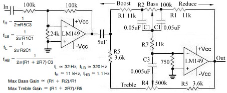
An audio tone control combines both a Base control and a treble control in the same circuit. This design combines an operational amplifier, as the active element, with a passive filter section. The design also uses a buffer amplifier between the external input to the circuit [not shown] and the actual tone control. The first part of the circuit, comprising the inverting amplifier, is really nothing more than a buffer.
The Operational amplifier is configured as an inverting amplifier, with the input applied to the minus input. However the circuit serves no function in regards to the tone control, unless a buffer is a requirement between the filter and presiding circuit.
A 0. 47uF input capacitor [value not shown] is used as a DC block with the value selected to pass audio frequencies. The 5uF capacitor at the output of the Op Amp is also a DC block and is not part of the filter circuit.
The passive components with comprise the filter are set up just as the previous circuits are, with a few variations. As noted in the diagram, the top part of the filter functions as the bass control and the bottom part of the filter functions as the treble control.
The values used in this design differ from the previous circuit. However the values will always be different from circuit to circuit as the designer selects different upper and lower 3dB points for the filter. As the diagram shows the base portion [ low pass filter ] of the circuit may be adjusted with a 3dB point between 32Hz and 320Hz.
While the 3dB of the treble section [ high pass filter ] may be adjusted from 1. 1Hz to 11Hz. The Base Adjustment and Treble Adjustment pages cover those portions of the circuit in more detail. The Op Amp used for this circuit example uses an LM149, while the previous circuit used an LM301. Although there are differences between different operation amplifiers, by design there meant to be universal parts. So in general many different parts may be substitute for the amplifier used in the actual schematic. In fact the LM148/LM149 series of parts is basically an upgrade or replacement for the universal 741 operational amplifier design.
The LM149 is a quad package Op Amp, so there are four individual amplifiers per package. Although only two amplifiers are used in the circuit above, or one if the buffer circuit is not required. Because this is a quad package, the device is available in either a 14-pin DIP Package [through-hole] or a 14-pin SOIC Package.
🔗 External reference
Related Circuits
The circuit presented is a remote control unit that utilizes radio frequency signals to manage various electrical appliances. This remote control unit is designed with 4 channels but can be expanded to 12 channels. Its design is notable for...
A rear fog lamp is mandatory for trailers and caravans to enhance visibility during foggy conditions. When the fog lamp is activated, the fog lamp of the towing vehicle must be turned off to prevent distracting reflections. To achieve...

The term VCXO refers to a Voltage Controlled Crystal Oscillator. The frequency of this oscillator can be fine-tuned by varying the control voltage. VCXO clock generators are utilized in a range of applications, including digital telecommunications. VCXO circuits are essential...
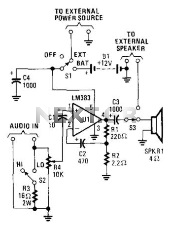
This audio power amplifier, built around an LM383 8-W audio power amplifier, is designed to enhance an audio signal to a sufficient level for audibility in high-noise environments. It is important to note that the LM383 requires a heatsink...
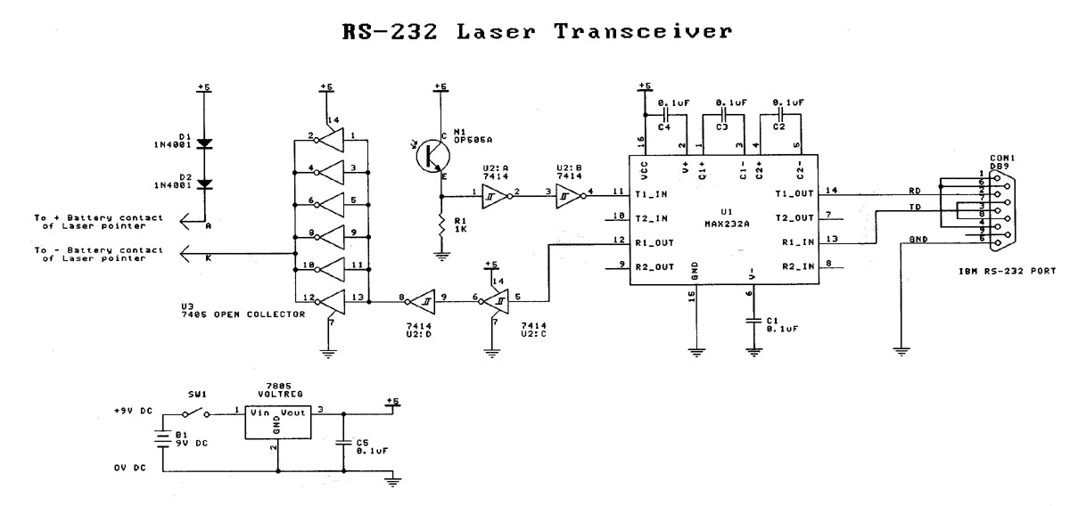
Laser based projects used to be expensive, until the development of solid state lasers. This project is designed for the entry level laser experimenter. The circuit allows any two computers with serial (RS-232) communication capability to communicate over 200...
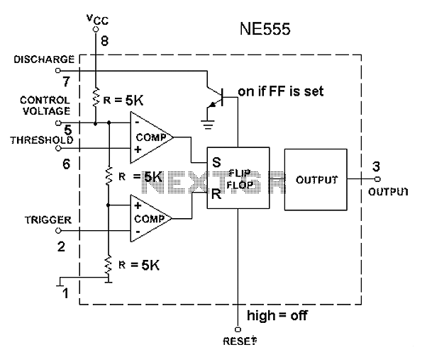
The 555 timer circuit, regardless of the manufacturer, has a consistent internal structure and performance. Various manufacturers produce different models of the 555 timer, including MC555, CA555, XR555, LM555, as well as domestic models like SL555, FX555, and 5G1555....