
UV/IR/Visible LED Flashlight with Intensity Control

The construction begins with an 8-inch long piece of standard-wall aluminum or PVC pipe with a 2 3/8-inch outer diameter. A 3/8-inch hole should be drilled 1.5 inches from one end for the potentiometer, and a 5/32-inch hole should be made another 1.5 inches away for the switch. A 1/4-20 hole is also drilled and tapped at the bottom to allow for tripod mounting.
The assembly of the electronics starts with soldering a size M coaxial power jack to the LED output of the LuxDrive model A011-D-V-700700mA FlexBlock Constant Current Driver. It is essential to use heat shrink tubing to insulate the center connector to prevent short circuits. The 20 kOhm linear potentiometer is then soldered to the LuxDrive driver, ensuring that turning the potentiometer clockwise increases LED intensity. All connections must be insulated with heat shrink tubing.
Next, the positive power rail circuit is assembled. The two positive battery terminals (each connected to two batteries in series) are soldered to the cathode of their respective diodes, ensuring correct polarity (the battery wire connects to the diode side without the band). The anodes of the two diodes are then joined and connected to a wire from the center pin of the external power input jack and the wiper contact of the switch. Insulation of all connections is critical.
The negative power rail is wired according to the schematic diagram, paying careful attention to which pin of the connector connects to the batteries and which connects to the negative input of the A011-D-V-700700mA FlexBlock driver. To maintain organization, small wire ties should be used to keep wires tidy.
To prepare the aluminum pipe cap, drill eight holes as indicated in the provided image. A photocopy of the heat sink's bottom can be temporarily glued to the cap for accurate hole placement. The holes should be slightly larger than the 4-40 stainless-steel screws used to attach the heat sink, and self-tapping stainless-steel machine screws are recommended.
Two 22 AWG wires should be soldered to the LED, with careful attention to polarity. The LED's mounting PCB serves as an effective heat dissipator, so it is necessary to heat the pads sufficiently for soldering. The LED should not be mounted to the heat sink before soldering the wires. The wires can then be passed through two of the heat sink channels, and the LED is mounted to the heat sink with a small amount of heat conductive grease applied between them. For a tighter beam, a reflector specifically designed for these LEDs can be hot-glued in place; however, it should be noted that these reflectors are optimized for visible light and may not perform well with infrared.Build a 10W LED flashlight that features swappable UV/IR/visible heads. We decided to document the build since this flashlight would fit nicely in a photographer`s kit for light painting, IR illumination, UV reflected photography, or UV fluorescence photography. Our flashlight is based on LedEngin`sLZ4-40_ series 10W LEDs. These are available in wavelengths ranging from theinfrared through the ultraviolet. White-light LEDs of different color temperatures are also available as part of this series. WARNING! This flashlight is capable of producing very powerful invisible radiation in the UV and IR. The eye`s protection reflexes do not work at these wavelengths, and may thus cause extensive damage if exposed to direct or specularillumination. In addition, UV at 365nm may cause damage to the skin. Never point this flashlight at anyone without taking proper precautions! The flashlight is powered from 4 9Vlithium batteries or from an external 14 to 30VDCpower supply (12VDC also works, but may not achieve full power output).
Start by constructing the flashlight`s body from an 8 ³-long piece of standard-wall aluminum or PVC 2 pipe-size (2 3/8 OD) tube. Drill a 3/8 hole 1. 5 ³ from one end for the pot, an a 5/32 ³ hole for switch another 1. 5 ³ away. We also drilled and tapped a 1/4 ³-20 hole on the bottom so that the flashlight could be mounted on a standard tripod.
Start to assemble the electronics by soldering the size M coaxial power jack to the LED output of the LuxDrivemodel A011-D-V-700700mAFlexBlock Constant Current Driver. Use a piece of heat shrink tubing to insulate the center connector to prevent shorting. Next, solder the 20 kOhmlinear pot to the LuxDrivemodel A011-D-V-700700mAFlexBlock Constant Current Driver.
Notice the connections such that the turning the pot clockwise will result in an increase in LED intensity. Insulate all connections with heat shrink tubing. Next, assemble the positive power rail circuit. The two positive battery terminals (each for two batteries in series) are each soldered to the cathode of its respective diode (pay attention to the polarity!
The battery wire is soldered to the diode side WITHOUT the band). The anodes of the two diodes are then soldered together to a wire from the center pin of the external power input jack and the switch`s wiper contact. Insulate everything very well using heat-shrink tubing. Wire the negative power rail as shown in the schematic diagram. Please pay attention to which pin of the connector goes to the batteries, and which one goes to the negative input of the A011-D-V-700700mAFlexBlock Constant Current Driver.
To complete the assembly of the power unit, use small wire ties to keep wires tidy. Start by drilling eight holes on the aluminum pipe cap as shown in the picture above. The easiest way to mark the position of the holes is to make a photocopy of the heat sink`s bottom and temporarily glue it to the cap. The holes must be just barely larger than the 4-40 stainless-steel screws that you will use to attach the heatsink.
Make sure that you use self-tapping stainless-steel machine screws. Next, solder two 22AWGwires to the LED. Pay attention to the polarity! The LED`s mounting PCB is an excellent heat dissipator, so you will need to really heat up the pads to get the solder to melt. Don`t even try mounting the diode to the heatsink before soldering the wires! Pass the wires through two of the heatsinkchannels, and mount the LED to the heatsink. Use just a tinybit of heat conductive grease between the LED and the heatsink. If you want a tighter beam from your flashlight, hot-glue one of the reflectors made for these LEDs. Please note that these reflectors are suitable for visible light only. They don`t do all that well with IR, and don`t w 🔗 External reference
Related Circuits
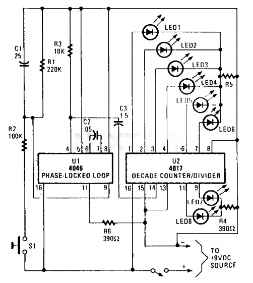
The circuit utilizes a 4046 Phase-Locked Loop (PLL) that incorporates a voltage-controlled oscillator (VCO), two phase comparators, a source follower, and a Zener diode to generate a low-frequency pulsed output of approximately 40 Hz. The frequency range of the...
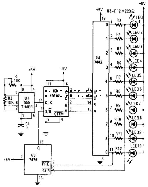
A 555 timer controls a 74190 up/down counter. The 74190 drives a BCD decoder driver 7442. The 7476 is utilized to reverse the count at 0 and 9, resulting in an up-down-up-down counting sequence. The circuit utilizes a 555 timer...
This is a single operational amplifier tone control circuit. The circuit functions as a hybrid low-pass, high-pass, and one-pole filter with both attenuation and gain. The single op-amp tone control circuit utilizes an operational amplifier (op-amp) to manipulate audio signals...
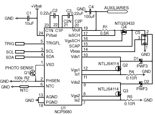
This white LED driver circuit project utilizes the NCP5680 high-efficiency white LED driver integrated circuit (IC). The NCP5680 supports dual power flash LED and torch operations. Its built-in DC/DC converter employs a highly efficient charge pump structure with operating...
The optically-controlled circuit plays a crucial role in urban street lighting and corridor illumination. By utilizing this circuit, lighting lamps can be automatically turned on and off based on ambient light levels, thereby reducing the need for manual control,...
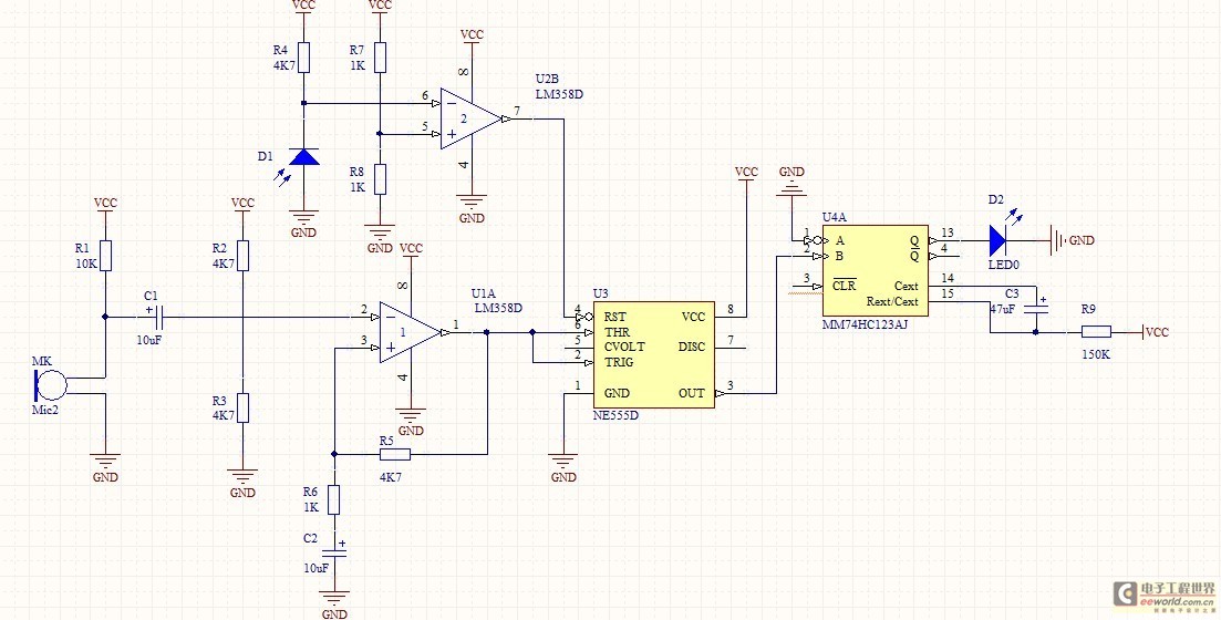
This project utilizes a small, common electret microphone to convert audio into an electrical signal. These inexpensive microphones are typically found in most PC headsets. The output from the microphone must be amplified and zeroed before it can be...