
Variable Frequency Sinewave Generator
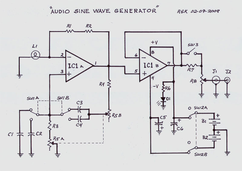
The sine wave generator operates on the principle of the Wien-bridge oscillator, which is known for producing low-distortion sine waves. The frequency range of 15 Hz to 150 kHz allows for versatile applications, including audio signal generation and testing of audio equipment.
The circuit design incorporates resistors and capacitors that form a bridge configuration, allowing for frequency adjustments by selecting different capacitors. The Wien-bridge oscillator typically includes a variable resistor that aids in stabilizing the amplitude of the output signal, ensuring consistent waveform characteristics.
In this particular design, the oscillator can be fine-tuned to achieve the desired frequency by adjusting the capacitor selection. The multiple capacitor options provide flexibility, enabling the user to select the appropriate value for the application at hand. The output can be taken from the oscillator's output node, which provides a clean sine wave signal suitable for various uses.
Power supply considerations should also be addressed, as the circuit typically requires a dual power supply to maintain proper operation across the frequency range. Additionally, incorporating a buffer amplifier at the output can improve the drive capability of the sine wave signal, allowing it to interface effectively with other circuit components or systems.
Overall, this sine wave generator circuit is an essential tool in electronic testing and signal processing, offering adjustable frequency output with low distortion characteristics, thanks to its Wien-bridge oscillator configuration.This sine wave generator is adjustable between 15 Hz to 150 kHz. The circuit is basically a Wien-bridge oscillator, with multiple capacitor selection. Here is. 🔗 External reference
Related Circuits
An alternative approach to utilizing operational amplifiers (op-amps) for power supply regulation is presented. This method necessitates an additional winding on the power transformer to provide the op-amps with a bipolar voltage of +/- 8 volts. The negative voltage...
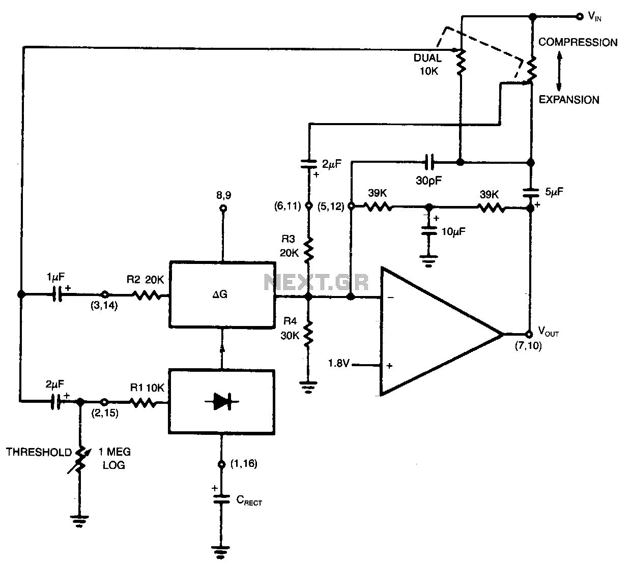
Compression and expansion ratios other than 2:1 can be achieved by the circuit shown. Rotation of the dual potentiometer causes the circuit connection to change from a basic compressor to a basic expander. At the center of rotation, the...

This design for a metal detector requires a variety of components and a few hours of work. Based on a CMOS 4011 integrated circuit, it is quite effective and versatile. The 250 kHz reference oscillator is constructed using two...
Any stepper motor can be utilized as a generator. Unlike other types of generators, a stepper motor generates a significant induced voltage even at low rotational speeds. A stepper motor operates by converting electrical energy into mechanical motion through a...
This single integrated circuit (IC) design is based on the Wien Bridge Oscillator, generating low distortion sine waves within a frequency range of 15 Hz to 22 kHz across two output voltage levels: approximately 0-250 mV and 0-2.5 Vrms....
This schematic is simple and easy to construct. The integrated circuit (IC) generates all the sound effects, with the output at Pin 3 being amplified by a transistor. A 64-ohm loudspeaker can be used instead of the 56-ohm resistor...