
audio sine wave generator

The Wien Bridge Oscillator circuit is renowned for its ability to produce stable sine wave outputs with minimal distortion, making it suitable for a variety of audio applications. The use of a TL082 dual operational amplifier enhances the performance by providing low noise and high gain characteristics, which are essential for maintaining signal integrity across the frequency range. The circuit's design employs a feedback mechanism that adjusts gain dynamically, allowing for consistent oscillation without external intervention.
The choice of lamp L1 is critical; its resistance characteristics play a pivotal role in the stabilization of the circuit's gain. The interaction between the lamp and resistors R1 and R2 forms a feedback loop that is sensitive to changes in load and temperature, which is beneficial for maintaining oscillation under varying conditions. The use of resistors R3 and R4 is equally important, as they define the frequency response of the circuit, ensuring that the output remains within specified limits.
In terms of physical assembly, attention to detail during the construction phase is crucial for ensuring reliability and performance. The specified dimensions for the printed circuit board and the enclosure components will facilitate proper fit and function. The use of high-quality materials, such as oak for the sides and aluminum for the front panel, will enhance the durability of the final product.
Overall, this circuit design exemplifies a practical application of the Wien Bridge Oscillator, combining theoretical principles with hands-on construction techniques to produce a functional audio generator. The careful selection of components and adherence to design guidelines will result in a robust and effective sine wave generator suitable for various audio testing and experimentation scenarios.This single IC circuit which is based on the Wien Bridge Oscillator, produces low distortion sine waves in the range of 15 Hz up to 22KHz in two ranges. The two output voltage ranges are from about 0-250mV and 0-2. 5Vrms. The image to the right shows an actual 1KHz output signal from the generator. The schematic below shows a TL082 dual operational amplifier being used as an oscillator and buffer amp. Signals at the output are adequate enough to drive eight ohm phones. Standby current drain is about 6mA from each battery. Two output jacks are provided for convenience The gain of this circuit is controlled by lamp L1 and resistors R1, R2. As the values of these resistors is raised, there is less negative feedback and thus, the circuit oscillates better up to a point where it becomes distorted.
Lowering the values of R1 and R2 too much will cause the circuit to stop oscillating. The general rule is that you want the cold ohmic value of the lamp to be about 1/3 the value of the resistor combination R1, R2. This lamp measures 105 ohms cold and it was found that resistance values of 216 ohms just allowed the circuit to oscillate, while 416 ohms and up caused signal clipping.
Thus a total value of 363 ohms was settled upon (330 ohms + 33 ohms). During oscillation, the lamp heats up a bit and its value raises to stabilize the circuit`s gain. Meanwhile, frequency is determined by pot R5 and the associated capacitors. It is the feedback to the positive input through these RC networks that causes oscillation at a particular frequency. The formula f=1 over 6. 28 x R x C may be used to determine oscillating frequency, should you wish other ranges. R3 and R4 simply limit the high end of each frequency range. For high output LEDs, use a 4. 7K resistor for R6. For standard LEDs, use a 1K resistor. The LED serves as an on/off indicator only. Regarding lamp L1, it does not have to be this particular one, however if you use another you will have to adjust the values of R1 and R2.
Many lamps were tried in prototyping, with the #1764 giving the best all around performance. Begin by cutting out the printed circuit board material to 5 1/2 in. wide by 3 3/4 in. deep. I personally, simply use the pattern on the right to mark all of the drill points with a punch and then draw the lines with a Sharpie pen and then etch. Mount components and solder. Cut two pieces of wood ( I prefer Oak) to in. thick by 3 in long x 2 ½ in. high for the sides. Cut a piece of. 062 aluminum to 5 ½ in wide x 5 in. high for the front panel. Finally cut a piece of white mat cardboard to 4 9/16 in. wide x 2 ½ in high for the dial plate. Bend two pieces of aluminum to form battery holders and attach them to the wood sides before any further construction.
Now assemble the entire unit and solder. 🔗 External reference
Related Circuits
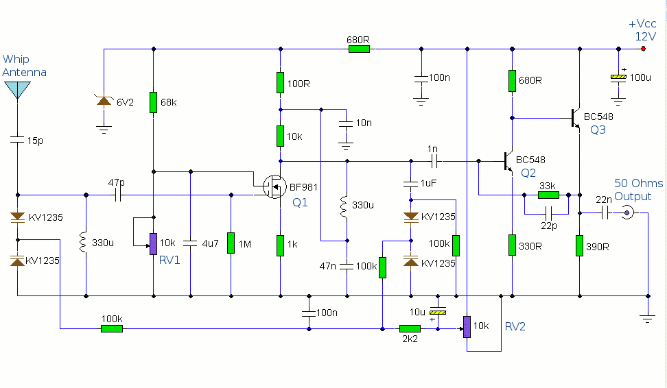
This circuit is designed to amplify the input from a telescopic whip antenna. The preamplifier is designed to cover the medium waveband from about 550KHz to 1650KHz. The tuning voltage is supplied via RV2, a 10k potentiometer connected to...
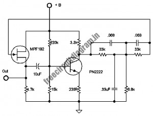
The following circuit illustrates a stable 60 Hz frequency signal generator circuit diagram. Features include a 0.068 µF capacitor incorporated within a feedback loop, allowing for DC-to-AC conversion. This circuit is designed to generate a stable 60 Hz sine wave...
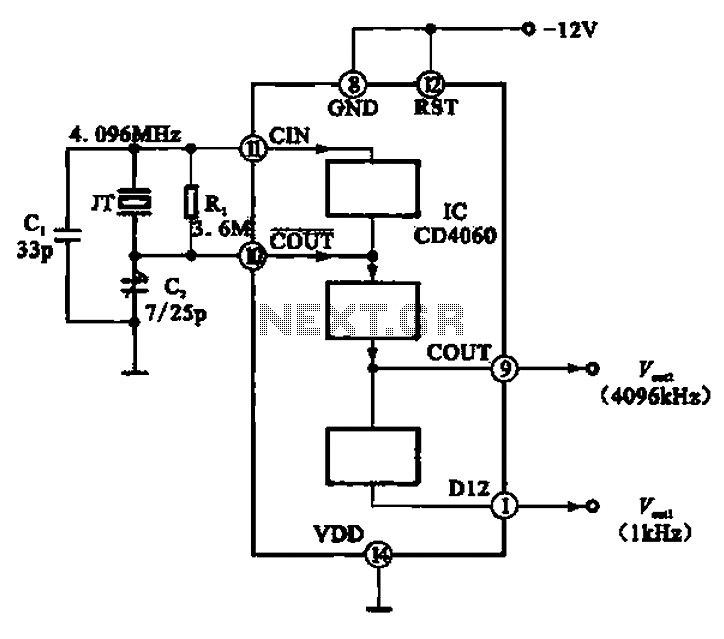
A 1 kHz square wave signal source circuit is illustrated using the CD4060 integrated circuit. The CD4060 operates with an external crystal oscillator and compensating capacitors such as C1 and C2. The internal oscillator circuit of the chip is...
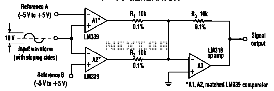
A simple frequency multiplier consists of two comparators and a summing amplifier that generate differential harmonic spectra. This circuit is capable of extracting harmonics from various waveforms, including sine, triangle, sawtooth, or other sloped waveforms. When a sloped-input waveform...
To generate a 1 MHz square wave, it is advisable to use a higher frequency crystal and divide it down for two reasons: (1) 4 MHz crystals are generally more affordable and easier to procure than 1 MHz crystals;...

Generating sine waves with controlled frequencies over a wide range is challenging when using RC or LC sinusoidal oscillators. However, this can be effectively achieved using a wideband digital square wave oscillator, a counter, and a weighted summing network....