
Variable PIN Attenuator
The RF attenuator circuit described employs a quad PIN diode array, specifically the HSMP-3816, which is known for its low insertion loss and high linearity in RF applications. The configuration includes two stages of diodes: the lower diodes, which are consistently biased at 1 mA, provide a stable impedance that is crucial for maintaining signal integrity across the specified frequency range. By adjusting resistor R5, users can fine-tune the input and output impedance to match the requirements of the RF system, ensuring optimal performance and minimizing reflections.
The upper diodes are influenced by a control voltage that can be varied from 0 to 10 V. At 0 V, the diodes enter a high-resistance state, effectively blocking the RF signal. As the control voltage increases, the diodes transition to a low-resistance state, allowing the RF signal to pass through with minimal attenuation. This feature is particularly advantageous in applications requiring dynamic control of RF signals, such as in communication systems or signal processing.
The design also highlights the efficiency of using a small control current to manage a higher power RF waveform, making this circuit suitable for integration into various RF applications where space and power efficiency are paramount. Overall, this RF attenuator circuit demonstrates significant utility in modern electronic design, particularly in systems that require precise control over signal levels.This is a very useful RF attenuator circuit which works from 300KHz to the 3GHz range based on the quad PIN diode array HSMP-3816 from Avego. The lower PIN diodes are biased at 1mA which gives about a 40 to 70 ohm impedance. R5 can be increased to increase the RF input and output impedances of the circuit. The upper diodes are biased by the contro l voltage which varies between 0 and 10V. The signal is essentially blocked when the control voltage is 0V and passes when the control voltage is high. The beauty of this circuit is that a small current can control a higher power RF waveform. Do you need help with an electronics design Daycounter provides contract electronics design services.
Contact us to give you a quote on your electronics design project. 🔗 External reference
Related Circuits
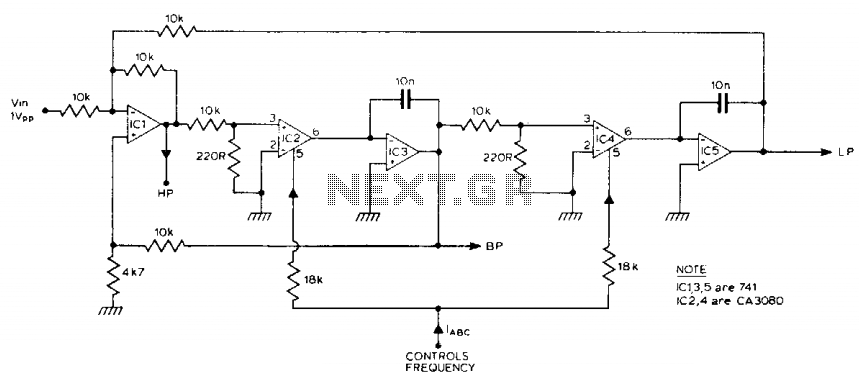
The filter generates three outputs: high-pass, bandpass, and low-pass. The frequency is linearly proportional to the gain of two integrators. Two CA3080 operational amplifiers (IC2, IC4) provide variable gain, with the resonant frequency being proportional to the current. Using...
A person visiting the website is interested in a DC voltage adjustable regulator that can output between 1.2V to 12V with a current capacity of 1-2A. Initially, the individual considers using the LM317 integrated circuit for this purpose. However,...
The input attenuator uses a commutating capacitor to cancel the input capacitance of the FET buffer (see DC-10 MHz amp schematic). The commutating capacitors are absolutely necessary to cancel the effect of the input capacitance to the DC-10MHz amplifier....
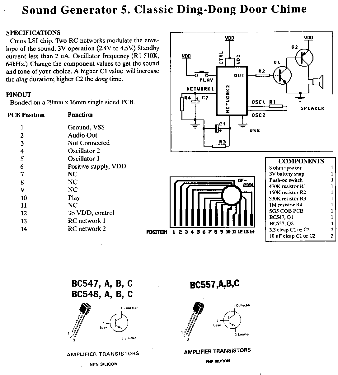
Adjust the component values in the two RC networks to achieve the desired tones. The circuit operates at a 3V low standby current. The kit includes 1 switch, a 1 Watt 8-ohm speaker, 2 AA battery holders, a COB,...
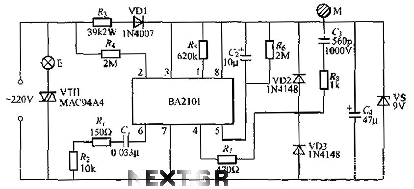
The BA2101 is a dimming controller utilizing an ASIC to create a barrel of light touch stepping. It is a non-constant lamp suitable for heir light. Each touch on the electrode sheet M can adjust the lamp brightness through...
The transformer can be selected based on the required maximum voltage and current output. Recommended options include: 36V, 40V, or 48V center-tapped configurations, with power ratings of 50VA, 75VA, 80VA, or 100VA. It is essential to mount Q4 on...