
Adjustable Attenuator for Oscilloscope
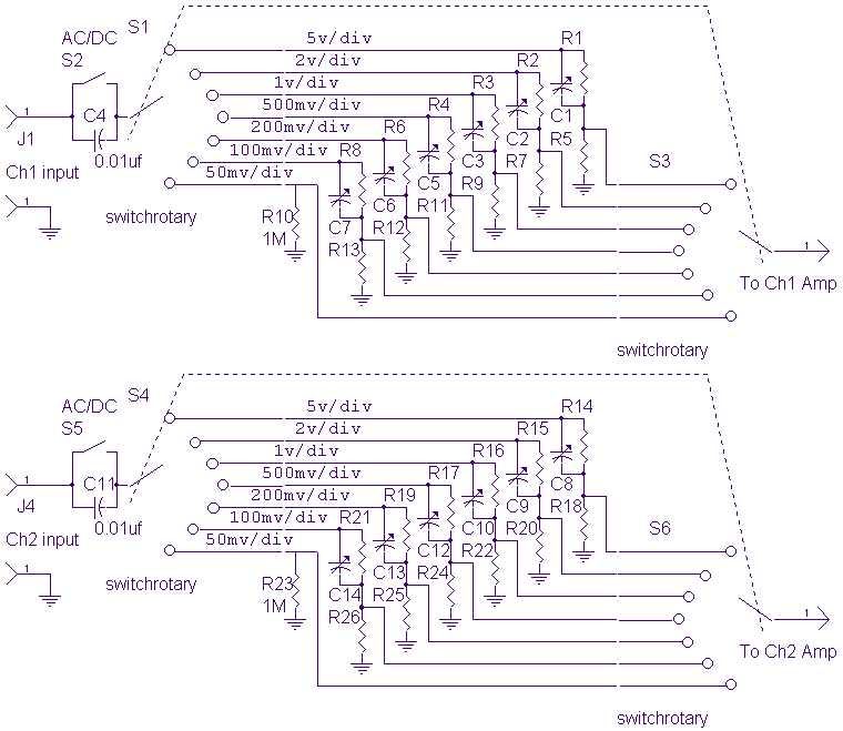
The described input attenuator circuit employs a commutating capacitor mechanism to effectively mitigate the input capacitance associated with the Field Effect Transistor (FET) buffer. This is particularly crucial for maintaining the performance of the DC-10 MHz amplifier, as excess input capacitance can adversely affect the frequency response and overall signal integrity.
In this circuit, the commutating capacitors are strategically implemented to ensure that they counterbalance the input capacitance, thereby stabilizing the input signal across the specified frequency range. The input resistance is maintained at a consistent level of 1 MΩ across all range settings, which is essential for ensuring that the circuit operates within the desired parameters regardless of the selected sensitivity scale.
The design mandates that all resistive components be selected to achieve this 1 MΩ input resistance, while also considering the ratios of these resistances. This ratio is critical as it determines the scale sensitivities, allowing the circuit to correctly attenuate the input signals according to the specified settings. Careful selection and arrangement of these resistors will enable the attenuator to provide accurate and reliable performance across its operational range.
Overall, the integration of commutating capacitors in conjunction with precisely chosen resistive elements forms a robust input attenuator design that is well-suited for applications requiring high-frequency signal processing while maintaining optimal input impedance characteristics.The input attenuator uses a commutating capacitor to cancel the input capacitance of the FET buffer (see DC-10 MHz amp schematic). The commutating capacitors are absolutely necessary to cancel the effect of the input capacitance to the DC-10MHz amplifier.
The theory of the commutating capacitors will not be discussed here. The input resistance is 1M ohm at all range settings. All resistances should be chosen to provide 1M ohms at any scale sensitivity. However the ratio of the resistances should also be chosen to provide the scale sensitivities shown below. 🔗 External reference
Related Circuits
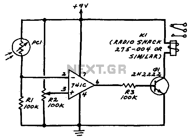
R2 sets the circuit's threshold. When the light intensity at the PCI's surface decreases, the resistance of PCI, a cadmium-sulfide photo-resistor, increases. This results in a decrease in voltage at the inverting input of the 741 operational amplifier. When...
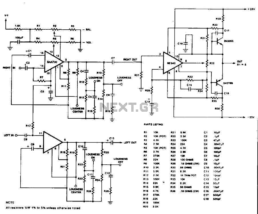
This circuit is an audio preamplifier that has balance, tone, and loudness controls. It should be suitable as an example of good design for audio applications. The audio preamplifier circuit utilizes the BAA730 and NE540 integrated circuits, which are...
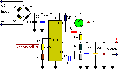
This power supply is designed as either an auxiliary or a permanent power supply for various common circuits that require a stabilized DC voltage ranging from 3 to 30V, provided that the current consumption does not exceed 3A. Additionally,...
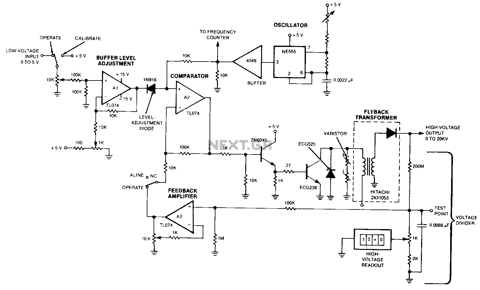
The output voltage varies approximately linearly up to 20 kV as the input voltage is adjusted from 0 to 5 V. A 5-0 potentiometer is used to tune the oscillator, optimizing the output voltage at the frequency of maximum...
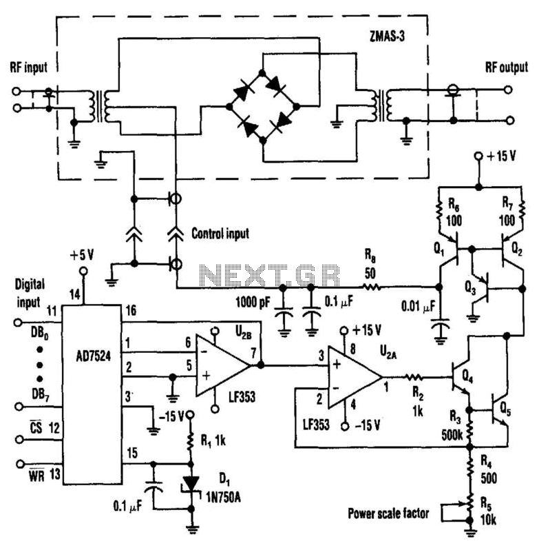
A balanced mixer functions as a control element in this circuit. An Analog Devices AD7524 D/A converter drives a voltage-controlled current source utilizing two LF353 operational amplifiers and several transistors to manage the balanced mixer, a Mini Circuits Lab...
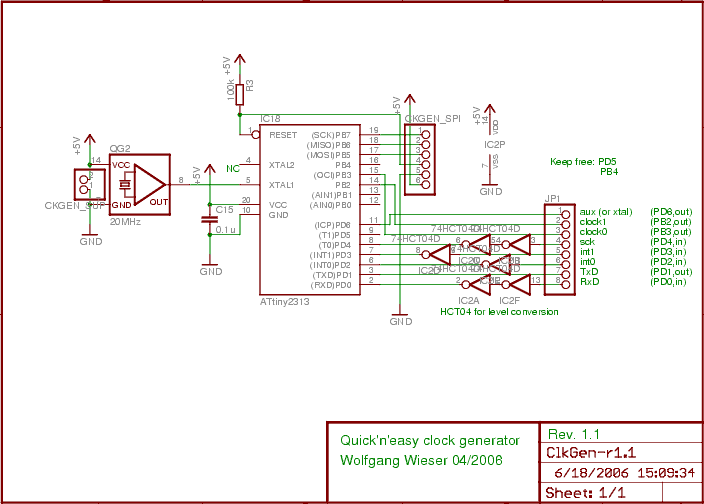
The design generates varying sampling clock write strobe pulses using an ATtiny2313 microcontroller from Atmel. For a 10MHz sampling clock, a 20MHz clock is required for the ATtiny2313, necessitating a power supply of 5V instead of 3.3V, which is...