
Variable speed electric motor bike circuit
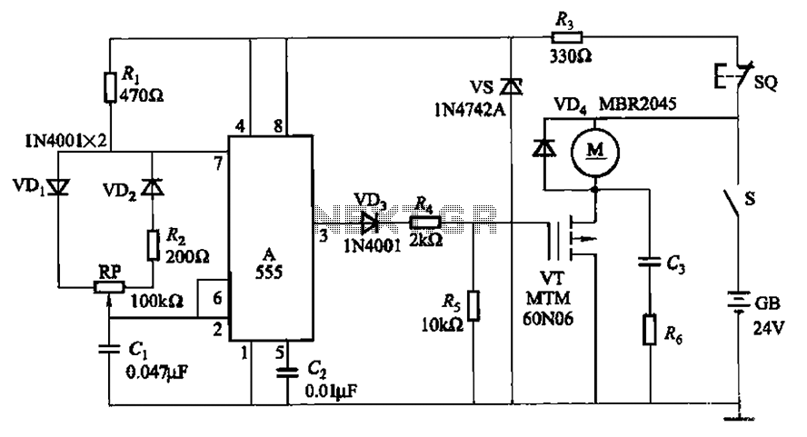
The circuit utilizes a 555 timer IC configured in astable mode to produce a square wave output. The adjustment potentiometer (RP) is integrated into the timing circuit, influencing the charge and discharge times of the timing capacitor. By varying the resistance of the potentiometer, the duty cycle of the square wave can be adjusted, which directly affects the average voltage supplied to the motor.
In this configuration, the 555 timer operates with two resistors (R1 and R2) and a timing capacitor (C). The values of R1 and R2 are fixed, while RP is variable. The duty cycle (D) of the output waveform can be calculated using the formula:
D = (R2 / (R1 + 2 * R2)) * 100%
As RP is adjusted, the ratio of R2 to the total resistance (R1 + R2) changes, thereby altering the duty cycle. This change in duty cycle results in a corresponding change in the effective voltage applied to the motor, allowing for precise speed control. The motor can operate from a complete stop (0% speed) to full speed (100%) depending on the position of the potentiometer.
The circuit should include additional components such as a diode for back EMF protection and possibly a transistor or MOSFET to handle higher current loads required by the motor. Proper decoupling capacitors should also be placed near the power supply pins of the 555 IC to ensure stable operation. This design provides a simple yet effective method for controlling motor speed using a widely available 555 timer IC.Adjustment potentiometer RP, can change by the 555 IC A New Zealand into a square wave duty cycle of the square wave, the motor speed to achieve the purpose of the speed range of O-l00%.
Related Circuits
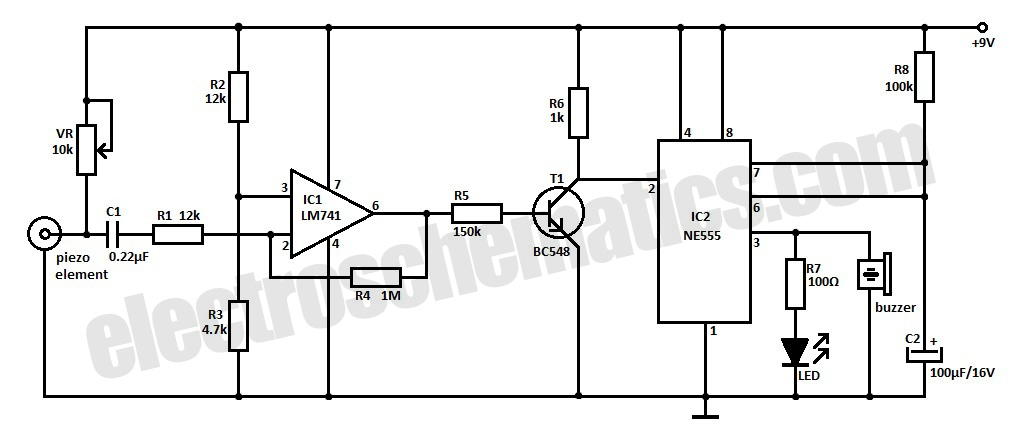
This is an ultra-sensitive earthquake detector circuit capable of sensing seismic vibrations. It can be utilized to detect vibrations in the Earth. The ultra-sensitive earthquake detector circuit is designed to respond to minute seismic vibrations, making it an essential tool...
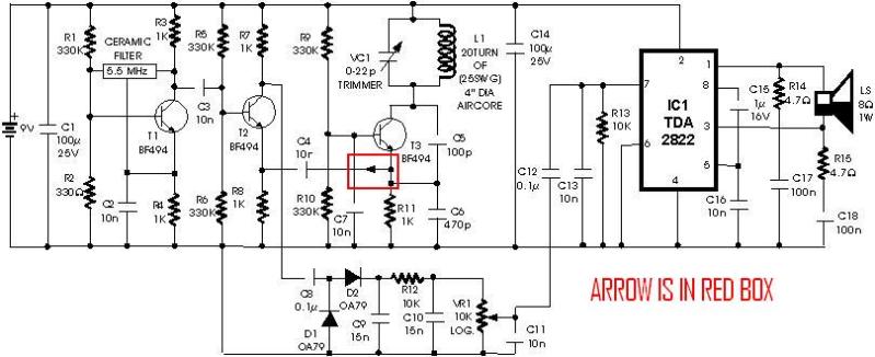
A schematic diagram for a metal detector has been found. The project does not need to be original and can be sourced from the internet. There are several questions regarding this schematic. One query pertains to a small arrow...
Crystal Y1 generates a fundamental frequency clock signal of 14.31818 MHz. U31 is a Dual Voltage Controlled Oscillator (VCO) that produces a 14.31818 MHz clock signal, referred to as the color clock, at pin 10. The output frequency can...
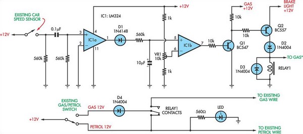
The following circuit illustrates a petrol gas switch sensor circuit diagram designed for a Pajero vehicle. It features a simple configuration utilizing the LM334 integrated circuit and operates automatically. The petrol gas switch sensor circuit is designed to monitor and...
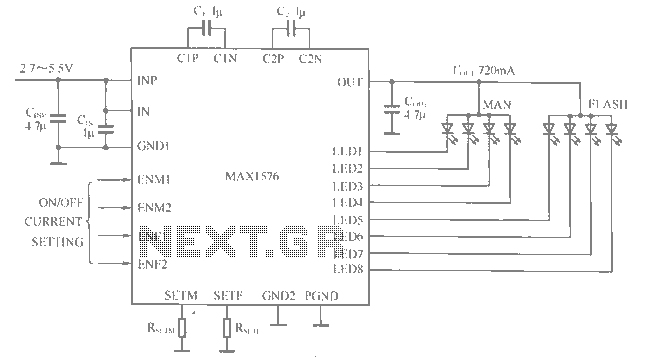
The MAX1516 charge pump drives up to 8 white LEDs with constant current regulation to achieve uniform light intensity, capable of delivering up to 30mA per LED for backlighting. The flash group LEDs (LED5 to LED8) are individually controlled,...
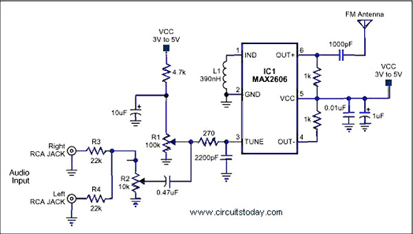
A simple single-chip FM transmitter circuit with a diagram and schematic using the IC MAX 2606, which is a high-performance voltage-controlled oscillator (VCO). The FM transmitter circuit utilizing the MAX 2606 is designed for efficient frequency modulation of audio signals....
Warning: include(partials/cookie-banner.php): Failed to open stream: Permission denied in /var/www/html/nextgr/view-circuit.php on line 713
Warning: include(): Failed opening 'partials/cookie-banner.php' for inclusion (include_path='.:/usr/share/php') in /var/www/html/nextgr/view-circuit.php on line 713