
Commodore 64 Clock Circuits
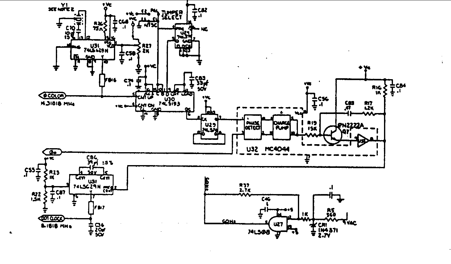
The circuit described includes several key components that work together to produce and manage clock signals essential for various electronic applications. The crystal oscillator Y1 is fundamental in establishing the base frequency, providing a stable reference point for the system. The Dual Voltage Controlled Oscillator (U31) is crucial for generating the necessary clock signals, including the color clock and the DOT clock. By utilizing R27, adjustments can be made to fine-tune the output frequency, ensuring the precision required in applications such as video processing or timing circuits.
The frequency divider (U30) serves to reduce the frequency from the color clock to a more manageable 2 MHz, which can be used for different timing requirements within the system. The D flip-flop (U29) further divides this signal down to 1 MHz, demonstrating how multiple stages of frequency division can be implemented to achieve various operational needs.
U32's role as a Phase/Frequency Detector is critical in maintaining synchronization between the different clock signals. By comparing the outputs of the D flip-flop and the phase 0 clock, it ensures that any phase discrepancies are corrected, thereby maintaining the integrity of the clock signals. The output DC voltage from U32 serves as a feedback mechanism to adjust the frequency control input of the VCO, allowing for dynamic tracking of the clock signals.
Overall, this circuit configuration exemplifies a well-structured approach to clock signal generation and management, utilizing a combination of oscillators, dividers, and phase detectors to ensure precise timing in electronic systems.Crystal Y1 develops a 14. 31818MHz fundamental frequency clock signal. U31 is a Dual Voltage Controlled Oscillator. The output on pin 10 is a 14. 31818 MHz clock signal called the color clock. R27 can be adjusted to obtain exact output frequency. U30 is a frequency divider that outputs a 2MHz signal on pin 6. U29 is a D flip flop which outputs a 1MH z signal on pin 9. U32 is a Phase/Frequency Detector which compares the output of the U29 to the phase 0 clock, and outputs a dc voltage on pin 8 that is proportional to the phase difference between the inputs. The second half of the Dual Voltage Controller Oscillator U31 generates an 8. 1818MHz clock signal called the DOT Clock. The VIC IC divides the DOT clock by eight and outputs this as the phase 0 clock on pin 17. The output of the Phase/Frequency Detector is applied to the frequency control input pin 2 of U31. This causes tracking of the dot clock and the color clock because one input, pin 4 of U32, is the phase 0 clock which is derived from the dot clock, and the other pin 1 of U32, is derived from the color clock.
Crystal Y1 develops the fundamental 16Mhz clock signal. U31 is a Clock Generator IC that outputs the 8. 1818MHz DOT clock on pin 6, and the 14. 31818 MHz color clock on pin 8. 🔗 External reference
Related Circuits
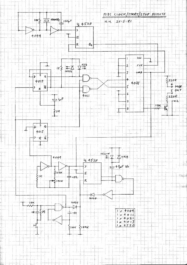
This circuit generates MIDI clocks and start/stop messages. The described circuit is designed to produce MIDI clock signals and control messages, which are essential for synchronizing musical devices that utilize the MIDI (Musical Instrument Digital Interface) protocol. The primary function...
A single beautiful giant ZM1042 NIXIE tube was acquired from Jim Oostveen, leading to the idea of constructing a single-digit NIXIE clock for Geert. The ideal case for this clock was found at a local IKEA store: a wooden...

In the first circuit, the BC548 transistor is configured as a Colpitts oscillator, with the frequency being adjusted through the insertion of a crystal. A high-quality crystal will generate high-frequency oscillations, and the output at the collector is rectified...
This device can also be referred to as an economical hearing aid, as it can be constructed using low-cost components. Although its performance does not match that of advanced commercially available hearing aids, it can effectively assist individuals with...
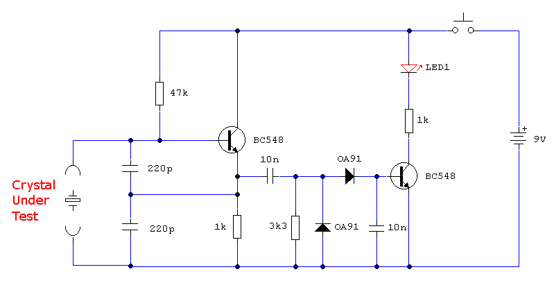
In the first circuit, the BC548 transistor is configured as a Colpitts oscillator, with the frequency being adjusted through the use of a crystal. A high-quality crystal will produce high-frequency oscillations, and the output at the collector is rectified...
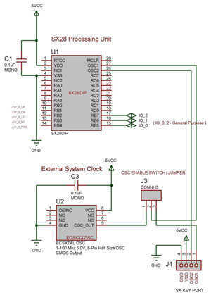
The SX 28 internal oscillator is not that fast, so an external oscillator can be hooked up to the processor as shown in the diagram to increase the operation cycles per second. The SX 28 microcontroller is designed with an...