
VHF antenna amplifier circuit diagram
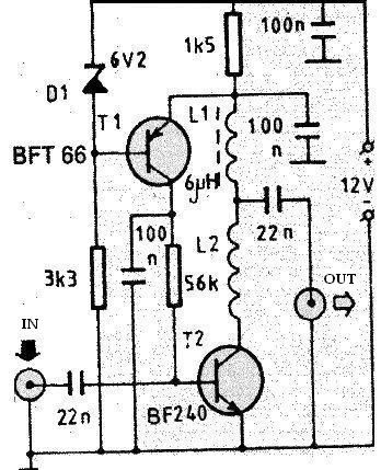
This RF antenna amplifier circuit is optimized for enhancing signal reception in the VHF frequency range, making it suitable for applications in both radio and television. The design incorporates a gain of 22 dB, which significantly boosts the incoming signal strength while maintaining low noise levels, crucial for clear audio and video output. The low noise figure of under 1.6 dB ensures minimal signal degradation, making this amplifier particularly effective in environments with weak signals.
The circuit utilizes two inductors, L1 and L2, which play a vital role in tuning and filtering the frequencies of interest. The L1 coil, rated at 6 µH, can be replaced with other inductors within the range of 5.6 to 6.8 µH, allowing for some flexibility in component selection based on availability and specific tuning requirements. The L2 coil, constructed as an air core with 5-6 turns, is designed to optimize the amplifier's performance by reducing losses associated with core materials. The dimensions of this coil are critical, with a length of 10 mm and a diameter of 5 mm, ensuring efficient electromagnetic coupling.
When assembling the circuit, it is recommended to use 0.25 mm copper wire for the L2 coil to ensure adequate conductivity and minimal resistance. The PCB layout should be compact and designed to minimize parasitic capacitance and inductance, which could affect the amplifier's performance. Additionally, placing the PCB close to the antenna within a metallic enclosure helps shield the circuit from external interference, enhancing overall signal integrity.
Powering the circuit requires a stable 12-volt DC source, which can be conveniently provided by a 12-volt battery. The low current consumption of under 10 mA allows for prolonged operation without significant energy depletion, making it suitable for portable applications. This design is ideal for hobbyists and professionals looking to improve VHF signal reception in various environments, ensuring reliable performance in both urban and rural settings.This RF antenna amplifier can be used for high frequency and VHF band ( for radio and TV) and will provide a 22 dB gain. This RF antenna amplifier electronic project has a very low noise, under 1. 6dB. L1 coil has a 6uH value, but can be used any coil for high frequency ( with a value between 5. 6 to 6. 8 u H). L2 coil is an air core type coil a nd it has 5-6 turns (10mm long and 5 mm diameter). For L2 coil can be used a 0. 25 mm Cuem wire. The pcb of this circuit must be placed near the antenna, in a small metallic box. This VHF antenna circuit must be powered from a 12 volts DC power supply circuit, you can use a 12 volt battery, because the current consumption of this circuit is very low under 10mA. 🔗 External reference
Related Circuits
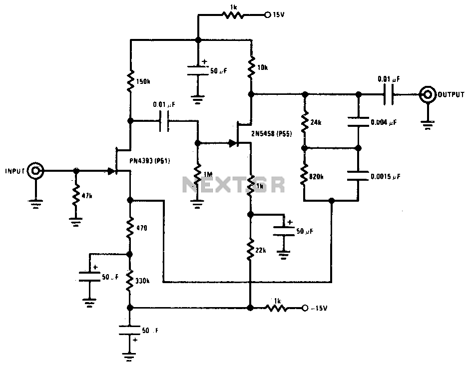
This preamplifier offers a loading ratio of better than -70 dB (referenced to a 10-ohm reluctance phono cartridge) and accepts millivolt input at 1 kHz. It has a dynamic range of approximately 35 dB of gain at 1 kHz...
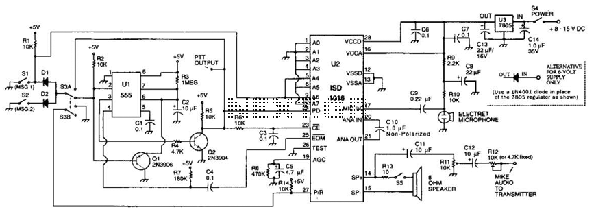
The circuit utilizes an ISD1016 audio record/playback chip from Information Storage Devices, Inc. to record and playback messages on demand. While it is primarily designed for use with transmitters, it can also serve as an electronic notepad or similar...
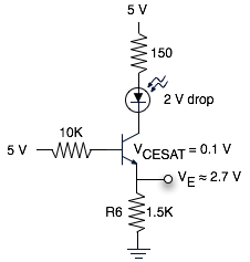
The schematic represents a relatively simple transistor circuit. Analyzing such schematics evokes memories of college days spent studying electrical engineering. However, the complexity of the schematic can be daunting after a long time away from the subject. To refresh...
The tube headphone amplifier in figure 1 is a high current mu follower, with a 12AU7 cathode follower driven by a 6CG7. Both sections of each tube are paralleled to minimize noise. It's a zero global feedback, OTL design...
There is an advantage in using continuously active PWM signals. The main reason is that the asynchronous frequencies of the PWM core and microcore can sometimes result in a shortened PWM pulse. The servo recognizes this as a command...
The Audio Research Corporation LS22 Line Stage Preamplifier was selected for this upgrade. The Audio Research LS22 Line Stage Preamplifier is a high-performance audio component designed to enhance the quality of sound reproduction in audio systems. This preamplifier features a...