
Servocore 2-motor walker circuit

The circuit described utilizes pulse width modulation (PWM) signals to control servo motors in a robotic walker application. The PWM signals from the microcore are continuously active, which helps mitigate issues caused by asynchronous frequencies between the PWM core and microcore, preventing premature pulse shortening. The design employs a quasi-bicore configuration, where the microcore outputs are routed through a series of four diodes (D3 to D8) to create master/slave bicore waveforms. This allows for independent control of the phase angles, which is crucial for achieving smooth motion in the servos.
The microcore generates four distinct PWM pulses (Nv1 to Nv4), which are responsible for controlling the direction and position of the servos. Each pulse corresponds to specific phases of motion: Nv1 is inactive during forward motion, allowing for longer pulses that drive the servos in a counterclockwise direction. The other pulses (Nv2, Nv3, and Nv4) are responsible for controlling the clockwise motion of the servos, with each pulse managing specific segments of the motion cycle.
To facilitate reversing the walker, the circuit incorporates a diode network that enables the selection of either Nv1 or Nv3 outputs, effectively creating a 180-degree phase shift in the PWM signals. This is achieved through a multiplexer arrangement using 74HC14 inverters, which also assists in managing the reverse delay. The use of diodes (D9 and D10) ensures that only the appropriate output is active at any given time, depending on whether the walker is moving forward or reversing.
Additionally, the circuit features a simple turning mechanism that introduces a bias into the PWM signals, allowing the walker to turn left or right. This is accomplished through a variable resistor (R9), which adjusts the bias for the rear motor PWM signals, thus influencing the walker’s trajectory. The stability of the walker is a critical factor in determining the effectiveness of the turning radius, and future revisions aim to enhance this functionality with additional inverter circuits for more precise control.
Overall, the design emphasizes the importance of PWM signal management and the role of diode networks in achieving complex motion control for robotic applications. The approach taken in this circuit can be adapted for various walker designs, showcasing versatility in the application of microcore technology in robotics.There is an advantage in using continuously active PWM signals. The main reason is that the asynchronous frequencies of the PWM core and microcore can sometimes result in a forshortened PWM pulse. The Sevo reconizes this as a command for a new positions and twitches toward that position. This makes the motion somewhat jerky on the original uServo4 c ircuit. In this application the microcore is actually used as a quasi- bicore. The microcore outputs are connected through 4 diodes to give the equivalent of master / slave bicore waveformsbut withindividual control of the rising and falling phaseangles. Since that can be used for turning a conventional " bicore " walker (but not the uServo walker), this techniquemay be exploited in other walker applications as well.
Normally the microcore generates 4 individual pulses from Nv 1 - Nv 4. The master / slave bicore waveforms are two ovelapping quadrature waveforms. The translatorsynthesizes the bicore waveforms in two parts using diodes D3 - D8 to OR the microcore outputs. During forward motion theoutput of Nv 1isnot used So when Nv 1 is active, the PWM pulses for both S1 and S2 are not influenced through diodes D3-8.
and the PWM s generate thelongestpulses driving bothservos to CCW. When Nv 2 is activeit controls duration of the first half of the S1 CW position, Nv 3 sets the second half of CW forS1 and the first half of CW for S2. Nv 4 controls the second half of CW for S2. Ifthe outputs of Nv 1and Nv 3 can be alternately selected, that would provide a 180 degree phase shift of the PWM signals required to reverse the walker.
The microcore to bicore diode networkalsopart ofthe reverse circuit to selectwhether the rear legs lead or lag by 90 degrees and therefore reverse the walker. The reverse circuit is a multiplexerto select either the output of Nv 1 or Nv 3 similar to theMx circuit but using two 74HC14 inverters and diodes to "steer" Nv 1 and Nv 3 pulses and to set the reverse delay.
During forward motion Nv 1 output is blocked byD10 while the output of Nv 3 is enabled byD9. Conversely when reversing, Nv 1 output isenabled byD10 while the output of Nv 3 isblocked byD9. The duration for the microcore Nv 1 - 4 pulses should be checked to be equal and slightly longer than thetime for CW and CCW rotation. The 74HC14 diode multiplexer / reverser may be used for other microcore applicatons. A somewhat primitive turning circuit has beenused toadd a left, right or neutralbias on the rear motor PWM pulse generatorcausing the walker to veer left, right or go straight.
The 1M pot (R9) is adjustedtheturning radius limited by the stability of the walker. The next revision will use the remaining spare inverters for a more positive turning circuit however for now, lest I suffer some serious mental indigestion, that`s it. Wilf`s original presentation of the ServoCore V5 material came in Yahoo group post #32315 here. Meanwhile, the presentation of ServoCore V6 came in Yahoo group post #xxxxx here. 🔗 External reference
Related Circuits
The inquiry pertains to the connection of lights that flash when a phone rings. This feature is particularly beneficial in noisy environments, such as workshops, where hearing the phone may be difficult. A device designed for this purpose is...
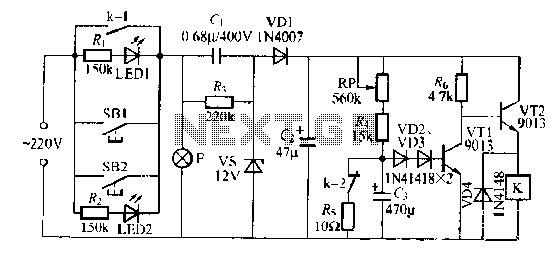
The lamp relay delay circuit is illustrated in Figure 7. Components S131 and SB2 are light buttons mounted in different locations. The lamp can operate with F. LEDs (LED1 and LED2) should be installed in SB1 and SB2 to...

This circuit is designed as a pocket-sized, high-performance audio oscillator. It can operate using a battery-powered version, which is feasible at a very low cost by utilizing a single quad op-amp to provide the entire active circuitry. The design...
Infrared remote controls are using a 32-56 kHz modulated square wave for communication. These circuits are used to transmit a 1-4 kHz digital signal (OOK modulation) through infra light (this is the maximum attainable speed, 1000-4000 bits per sec)....

This circuit represents a negative resistance configuration. All previous circuits utilize RC time constants to achieve resonance. LC combinations can also be employed, providing good frequency stability, high Q factor, and rapid startup. In this circuit, a signal input...

The circuit diagram of the Swallow CS37-2 type color TV illustrates the feeding tube configuration. The filament voltage is supplied by the line flyback transformer, with a current-limiting resistor R523. The accelerating voltage is managed by D502, which rectifies...