
VHF FM Crstal Set Radios
Phase-sensitive detectors are essential components in communication systems, particularly for demodulating FM signals. The operation of these detectors relies on comparing the phase of the incoming FM signal with a reference signal derived from the same source. The resonant circuit or delay line plays a crucial role in this process, as it helps maintain the necessary phase relationship to accurately detect frequency deviations.
The choice of the diode is critical in the design of the detector. The 1N34 diode, known for its ability to operate effectively at high frequencies, provides a balance of performance and availability. However, variations in manufacturing can lead to differences in internal resistance and capacitance, which can significantly affect the detector's performance. Selecting a diode with low internal resistance minimizes signal loss, while low capacitance ensures faster response times, making the detection of rapid frequency changes more reliable.
Richley's design, which utilizes a coaxial resonator, is noteworthy for its simplicity and effectiveness. The coaxial resonator's geometry allows for a high Q factor, which is essential for filtering out unwanted signals and enhancing the selectivity of the receiver. The quadrature detector arrangement he proposed, involving two diodes, is particularly effective for extracting the audio signal from the modulated carrier wave.
The decision to transition from a coaxial resonator to a helical resonator reflects practical considerations in construction and performance. Helical resonators can offer similar performance characteristics while being easier to implement in a compact form factor. The modifications made during the prototype phase demonstrate the iterative nature of electronic design, where performance testing leads to refinements in the initial concept.
The integration of the detector output with an audio mixer allows for real-time audio processing, enabling the observation of the receiver's performance. The ability to hear stations through sensitive headphones further validates the effectiveness of the design. The ongoing development of a personal design using Lecher lines indicates an exploration of alternative methods for frequency discrimination, showcasing the continuous pursuit of improved performance in radio frequency applications.
In conclusion, the combination of advanced diode technology and innovative resonator designs plays a pivotal role in the effectiveness of phase-sensitive detectors for FM signal demodulation. Future enhancements, including the addition of a beam aerial and audio amplifier, may further improve reception quality and expand the capabilities of the receiver system.Phase-sensitive detectors usually take the difference between an input FM signal and the same signal after it has passed through a resonant circuit, or through a delay line. A 1N34 should work fine to detect 100MHz, but not all 1N34 diodes are made alike. One with low internal resistance and low capacity would be best. Some fancy shottky diodes may have too much internal resistance. A few months ago I was looking for this same information, and was surprised how difficult it was to find any information on FM crystal sets using a frequency discriminator type detector. I finally managed to locate an article written by Ed Richley. The article was in two parts and appeared in the January and March 1996 editions of The Xtal Set Society Newsletter.
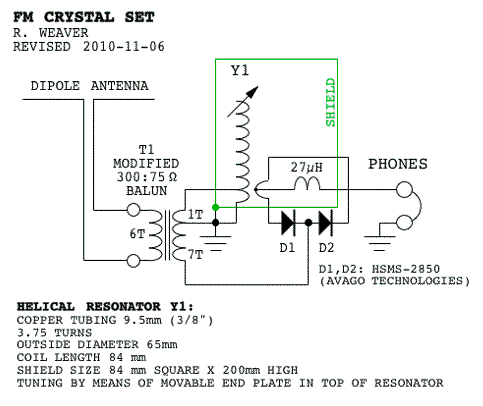
Ed`s design was quite ingenious, using only a single tuned circuit a coaxial resonator to achieve the required high Q, and two diodes in a quadrature detector arrangement. Perhaps this was the article Bryce was thinking of I had intended to build a copy of the Richley receiver, but concluded that a helical resonator would be more practical than a coaxial resonator.
So, that was the approach I took. By the time I finished constructing the prototype, I`d also made some other changes to the circuit. I`ve also posted a YouTube video showing a short demonstration of the receiver. In the demonstration, the detector output is fed into the microphone input of an audio mixer. However, all of the stations which can be heard in the video are also clearly audible with sensitive headphones. I started to make my own design using Lecher lines, but haven`t completed the phase discriminator, so all I get is (faint) distorted sound.
I purchased the Agilent diodes mentioned and they seem to work way better than anything else - even WW2 radar diodes, like the 1N21 etc (On tests using a signal generator). The completed set may need a beam aerial and possibly an audio amp. 🔗 External reference
Related Circuits
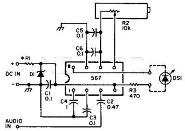
An NE567 tone decoder, tuned to the transceiver's CW offset frequency, ensures that the transceiver will be transmitting on the same frequency as the received CW signal. Simply tune the transceiver so that the LED lights. Eight to 13...
This operational amplifier (opamp) is available at a low cost. The AD8099 is a very fast opamp with a slew rate of 1600 V/µs and features high-impedance inputs with low input capacitance. Its bandwidth is sufficiently large that at...
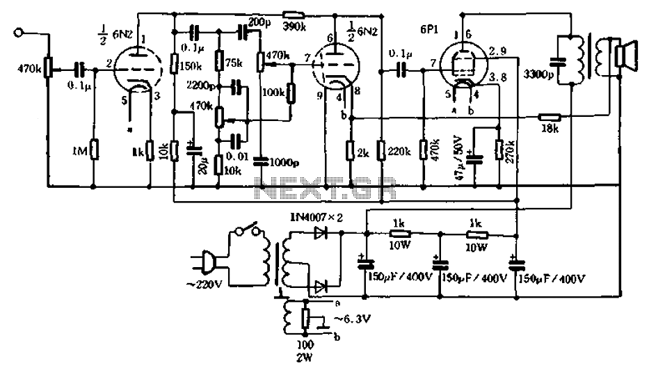
2W resistors can be used with metal or carbon film resistors and optional paper capacitors, polypropylene capacitors, rated for 400V. A selection of different media is available in various configurations. Although there is no established polarity for vintage paper...
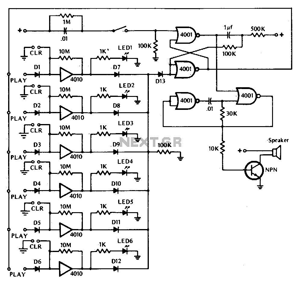
This game tests a player's reaction time. It is activated by closing switch SI, which starts the tone generator and arms the circuit. The touchplate, labeled PLAY in the diagram, consists of two metal strips about 1/16th inch apart....
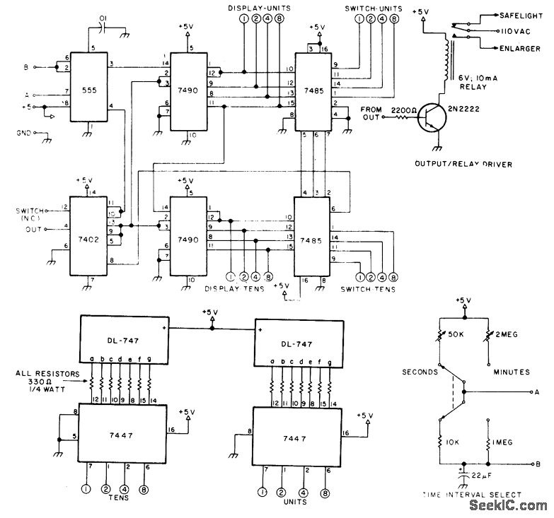
The circuit provides timing capabilities ranging from 1 second to 99 seconds and from 1 minute to 99 minutes, featuring a 2-digit LED indicator that displays the elapsed time. The desired timing interval is set using BCD thumbwheel switches....
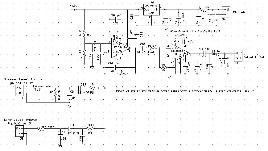
The audio mixer allows for easy comparison of various receivers by adjusting the gain controls without the need for switching. This setup simplifies A/B comparisons since all receivers are connected to the same antenna. Previously, different speakers were used...