
A 20 Input Audio Mixer for Multiple Receiver Setups
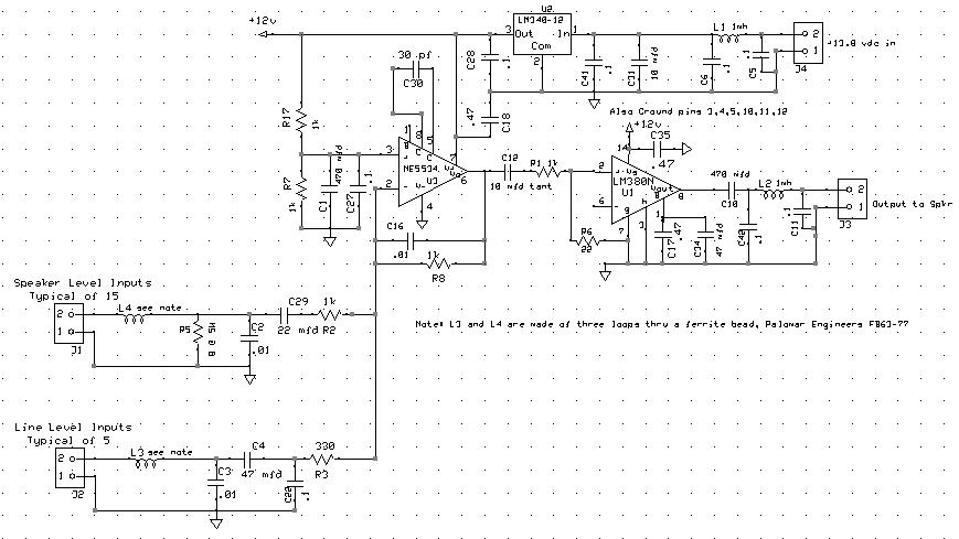
The audio mixer circuit is designed to facilitate the integration of multiple receivers into a single audio output system. The core of the mixer consists of a summing amplifier stage that combines the audio signals from various inputs. Each input is equipped with a resistor that determines the gain based on the input type—8 ohms for amplified outputs and 600 ohms for line-level signals. This configuration allows the mixer to handle different output characteristics from various receivers, such as the R390A and the Collins S line, which provide both types of outputs.
The summing amplifier stage is critical in ensuring that the mixed audio signal maintains fidelity and low distortion levels. The design employs a high-quality operational amplifier that is capable of delivering sufficient output power while maintaining a low noise floor. The choice of components, particularly in the input stage, plays a crucial role in minimizing noise and ensuring stability against external RFI.
Ferrite beads are strategically placed at each input and output connection to suppress high-frequency noise that may interfere with audio quality. Additionally, the use of high-quality bypass capacitors further enhances the circuit's immunity to RFI, thereby ensuring that the audio output remains clear and undistorted.
To optimize performance, the layout of the circuit is designed to minimize lead lengths, particularly around the inputs and power connections, which are the most susceptible to noise and interference. This careful consideration in design contributes to the overall effectiveness of the mixer, allowing for a seamless listening experience across multiple receivers.
In summary, the 20-input audio mixer serves as an efficient solution for audio management in multi-receiver setups. Its thoughtful design and implementation ensure that users can easily switch between receivers without the hassle of traditional switching methods, while maintaining high audio quality and low noise levels.Because of this audio mixer, I can compare the various receivers just by twiddling the gain controls. No switching required. Makes A/B comparisons a snap. (They are all driven by the same antenna). All of this used to be easy I just used a different speaker on each radio. However, once the receiver count soared up through 6 or 7, this solution started to lose its luster. Not only the cost, but also the space, consumed by all these speakers seemed to be getting out of whack. So another solution began to seem attractive. I put up with various frustrating switching arrangements for years before I got around to doing anything about it. This desire to listen to multiple rigs at once led me to develop a 20 input audio mixer. I run the audio from each receiver to the mixer, which then drives one speaker typically a Collins 312B-3.
This allows me to listen to whatever radios I want without worrying about any switching. I still have several speakers to choose from, but whichever one I use is driven by the mixer and, therefore, all the receivers. Some of the mixer`s inputs are 8 ohms and directly accept amplified outputs that would normally be connected to speakers.
Other inputs are 600 ohms and accept line level signals. Some receivers, like the R390A, have only a 600 ohm line level output. Others such as the Collins S line - have both types of outputs. I use whichever outputs exhibit less distortion. The design has been very successful. The mixer provides adequate output power (up to a couple of watts) with very low noise, and is nearly bullet proof with respect to RFI. The noise delivered to the speaker when all the radios are connected but turned off is only about 6 microwatts, which is just barely audible when I put my ear directly on the speaker grill and the room is quiet.
I tried to keep leads very short in the vicinity of the circuit`s most vulnerable areas - the inputs at each amp and the power connections to the amps. It seems to have quite well. However, I still find myself thinking about looking around for even lower noise amps. But I do realize that noise reduction then might be becoming an obsession. Oh, well. Each input and output is protected from RFI with a ferrite bead and a high quality bypass capacitor. The speaker level input is terminated with an 8 ohm 5 watt resistor. Then each signal is connected to the summing junction through a resistor. The value of this resistor sets the gain for that input, so the value of the input resistors are different for each of the two types of inputs reflecting the different voltage levels presented to those two types of inputs at any given reference level of sound pressure.
The Summing amp stage: These input resistors are all connected to 🔗 External reference
Related Circuits
A line follower robot, abbreviated as LFR, is an autonomous robot designed to optically follow a line drawn on the floor. This involves the robot moving along an arbitrary line using a component known as a line sensor. A...
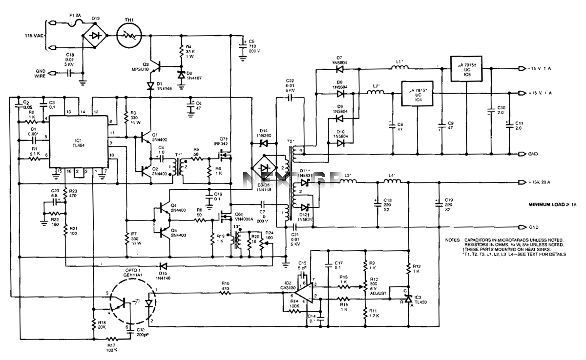
The power supply employs two VN4000A 400-V MOSPOWER FETs configured in a half-bridge arrangement. It provides outputs of +5 V at 20 A and ±15 V (or ±12 V) at 1 A. The low-current outputs utilize linear three-terminal regulators,...
The circuit operates from a 5-V supply and has a current consumption of 2 mA. The output functions as a current source that can drive or suppress a current exceeding 75 mA with a voltage swing of 4.5 V....
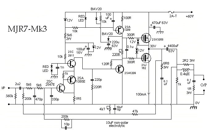
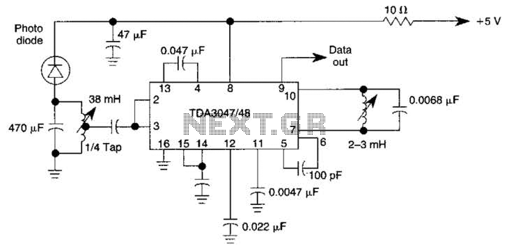
The Electronics Schematic Diagram MJR7-Mk3 Mosfet MJR6 page includes distortion extracted using the nulling method with a speaker load and a music signal to demonstrate that these designs have no audible distortion in normal use. The MJR7 has even...

The schematic for this project flows naturally from left to right, starting with the antenna and the regenerative receiver front-end, followed by amplification stages, and concluding with the 555 timer. This regenerative receiver front-end is commonly found in circuits...
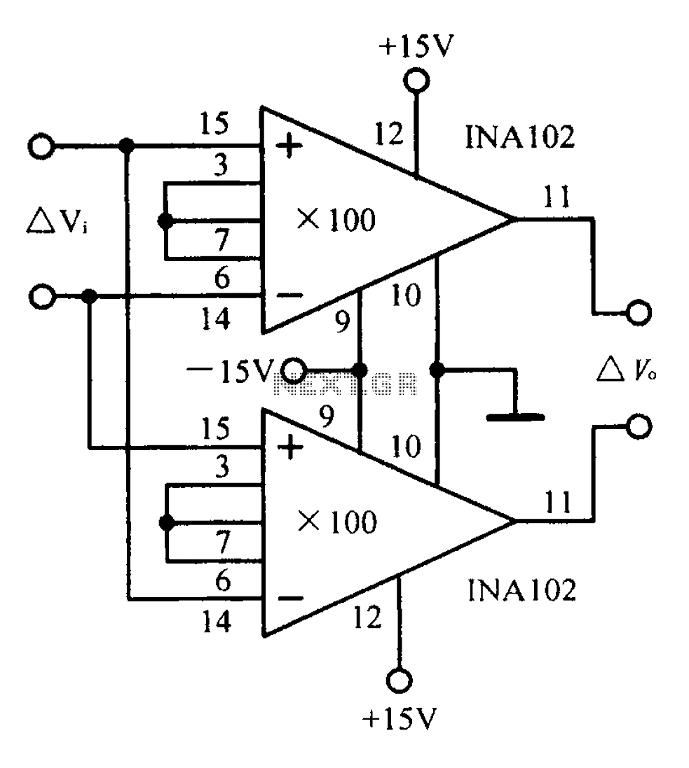
A differential input differential output amplifying circuit diagram. A differential input differential output (DIDO) amplifier is a type of operational amplifier configuration that is designed to amplify the difference between two input signals while rejecting any signals that are common...