
video amplifier circuit
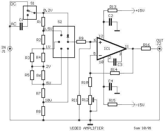
The video amplifier circuit utilizing the LH0032 operational amplifier is designed for high-speed signal processing, making it suitable for applications requiring rapid response times, such as video signals. The specified components, including resistors and capacitors, are selected to optimize the amplifier's performance, ensuring low noise and high fidelity in the output signal. The use of a trimmer potentiometer allows for fine-tuning of the circuit, which can be essential for achieving the desired output characteristics.
The audio/video modulator circuit serves a critical function in converting composite audio and video signals into a UHF TV signal, facilitating compatibility with standard television receivers. This conversion is essential for transmitting video signals from cameras or other sources to televisions, making it a valuable component in video broadcasting and monitoring systems.
The thermocouple amplifier circuit employing the CA3193 is engineered to provide precise amplification of low-level thermocouple signals, which are often in the millivolt range. The high gain of 500 times ensures that even minimal temperature changes can be accurately detected and measured. The use of high-value resistors in the circuit safeguards against signal loss due to open thermocouples, ensuring reliability in temperature sensing applications.
The LM3886 power amplifier circuit is noteworthy for its ability to deliver significant power output, making it suitable for driving speakers in various audio applications. The parallel configuration of two LM3886 chips enhances the overall power handling capability, allowing for greater audio output without distortion. This design is particularly beneficial in high-demand audio environments, such as home theater systems or live sound reinforcement.
The EL34 tube amplifier circuit highlights the enduring popularity of vacuum tube technology in audio applications. The EL34 tube is revered for its warm sound characteristics and ability to produce rich harmonics, making it a preferred choice among audiophiles. The inclusion of a power supply circuit diagram ensures that users can implement the design effectively, providing the necessary voltage and current for optimal performance.
The TDA2822-based stereo headphone amplifier circuit exemplifies compact design for portable audio applications. Its ability to deliver adequate power to headphones while operating on a low voltage supply makes it ideal for battery-powered devices. This circuit design is particularly useful in consumer electronics, where space and power efficiency are critical considerations.This is schematic diagram of a video amplifier circuit, built based very high speed opamp IC LH0032. Parts List: R1 = 15K ©+15K © R2-3-4 = 10K © R5, R6, R7, R8, R9 = 1K © R10 = 820 © R11 = 1M © R12 = 100 © trimmer R13, R14, R15 = 47 © R14 = 10K © C1 = 10uF 63V MKT C2, C3, C4 = 100nF/63V C3 = 4. 7pF. This is the circuit diagram of audio/video modulator. Th e circuit will convert an audio and video signal into a UHF TV signal. It`s desired to connect a video signal originating from a camera or other video source to a normal TV set. The audio and video signal is converted into a UHF TV signal so. Above circuit design is thermocouple amplifier circuit using CA3193 operating amplifier. The CA3193 is an excellent choice for use with thermocouples. In the circuit, the CA3193 amplifies the generated signal 500 times. The three 22M © resistors will provide full-scale output if the thermocouple opens. The CA3193 are ultra-stable, precision instrumentation, operational amplifiers that employ. This is the 100 Watt power amplifier circuit based power amp chip LM3886. Single chip of LM3886 is able to generate power output up to 68W. In this circuit, the two of LM3886 are paralled to gain more powerful amplifier output. This amplifier can deliver about 50W into a 8-ohm speaker and 100W into a. The following diagram is the circuit diagram of 20W power amplifier which build based tube component EL34.
EL34 is very famous tube and great for power tube amplifier. The circuit above is complete circuit contains tube amplifier circuit diagram and power supply circuit diagram. To make the stereo channel amplifier, build the similar amplifier circuit. Above circuit diagram is the schematic of 1W stereo headphone amplifier. The circuit is built based TDA2822, designed for use in portable players, radios and other common electronic devices which can use headphone for the audio output.
A 3V power supply/battery can be used to drive headphones providing 20mW in 32 Ohms per channel. This. 🔗 External reference
Related Circuits
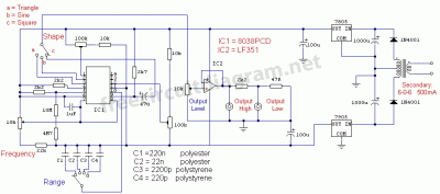
This is a simple function generator built around a single 8038 waveform generator IC. The circuit is capable of producing sine, square, or triangle waves within a frequency range of 20Hz to 200kHz. The function generator circuit utilizes the 8038...
This digital DIY tachometer for bicycles utilizes two reed switches to gather speed information. The reed switches are positioned near the wheel rim, where permanent magnets are mounted on the wheel spokes. As the spokes rotate, the magnets pass...
This compact water sensor alarm circuit emits a loud warning sound when a humidity sensor detects the presence of water. The circuit utilizes the low-power comparator LM1801 from National Semiconductor. A fixed reference voltage for the integrated circuit is...
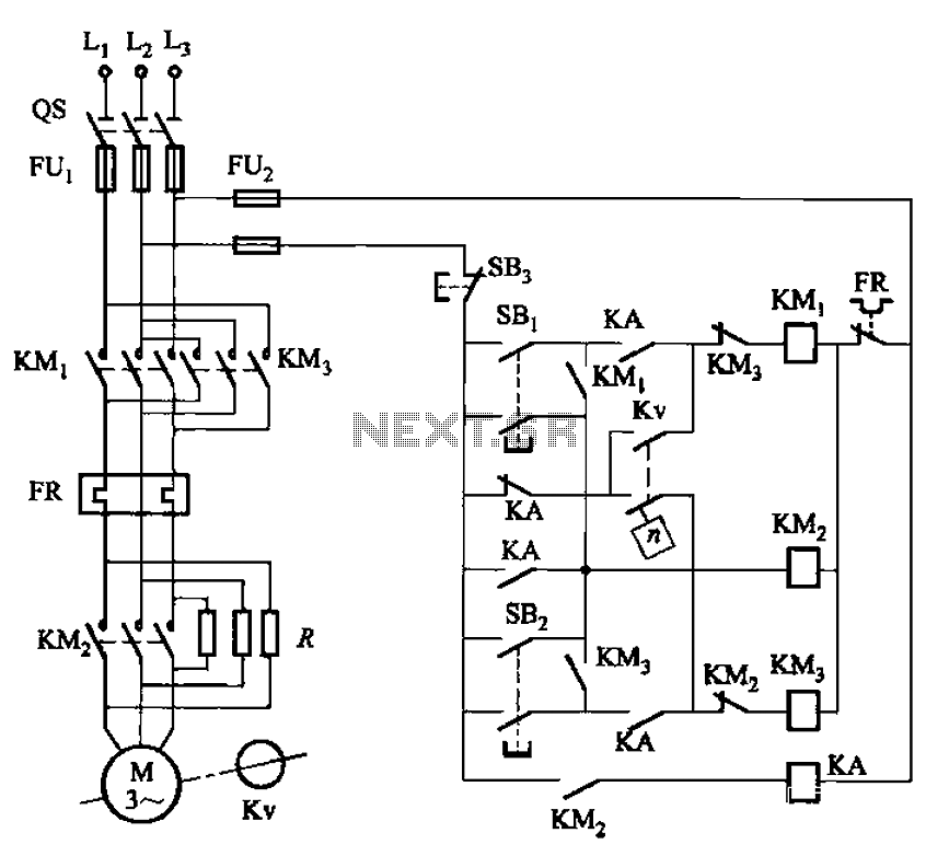
The circuit shown in Figure 3-129 is the C650-2 lathe brake control circuit, utilizing a speed control relay. The C650-2 lathe brake control circuit is designed to manage the braking mechanism of a lathe machine effectively. This circuit incorporates a...
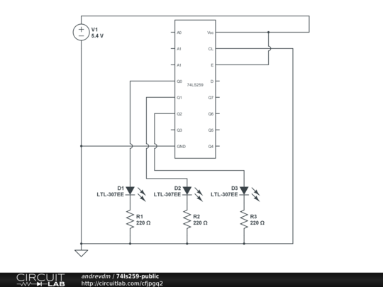
The objective is to utilize a 74LS259 8-bit addressable latch without the involvement of a microcontroller, in order to fully comprehend the wiring and functionality. The 74LS259 is an 8-bit addressable latch that is commonly used in digital circuits for...
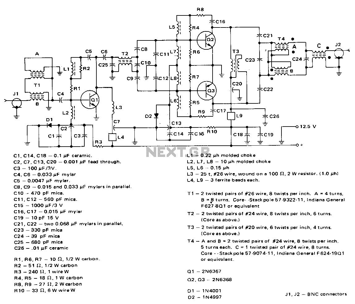
This amplifier employs a 2N6367 transistor as a driver along with a pair of 2N6368 transistors. The 2N6367 is rated for a maximum output of 9 W (PEP) and is required to deliver 5 W (PEP) at 30 MHz,...