
Simple Function Generator Circuit
The function generator circuit utilizes the 8038 integrated circuit, which is known for its precision and versatility in waveform generation. The IC can be configured to output three distinct types of waveforms: sine, square, and triangle. The frequency range of 20Hz to 200kHz allows for a wide variety of applications, including signal processing, testing of audio equipment, and simulation of various electronic signals.
The 8038 IC operates by utilizing external resistors and capacitors to set the frequency and waveform shape. The output can be adjusted by changing these external components. A potentiometer is typically included in the design to allow for fine-tuning of the frequency, providing an easily adjustable output.
In addition to the basic waveform generation, the circuit may include additional features such as amplitude control, offset adjustment, and output buffering to ensure that the generated signals are stable and suitable for driving other circuits or devices.
Power supply requirements for the 8038 are typically in the range of ±15V, which is standard for many analog circuits, ensuring compatibility with a wide range of electronic components. Proper decoupling capacitors should be included near the power supply pins of the IC to minimize noise and ensure stable operation.
Overall, this simple function generator circuit is an effective tool for generating various waveforms for testing and experimentation in electronic applications. Its straightforward design makes it accessible for both novice and experienced engineers.Here is simple function generator. Built around a single 8038 waveform generator IC, this circuit produces sine, square or triangle waves from 20Hz to 200kHz in. 🔗 External reference
Related Circuits
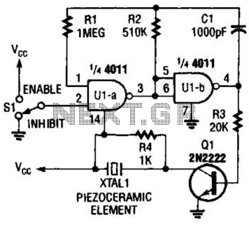
A CMOS gate and transistor buffer can be used as an effective driver for a piezoelectric transducer. The use of a CMOS gate combined with a transistor buffer offers a robust solution for driving piezoelectric transducers. CMOS technology, known for...
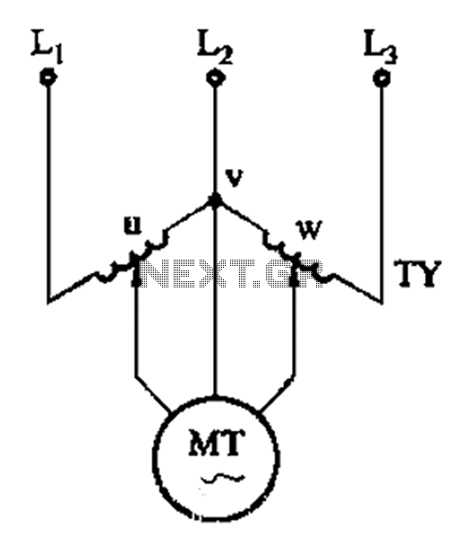
The circuit shown in Figure 3-177 utilizes two single-phase voltage regulators connected to a V-shaped configuration of single-phase regulators. This setup allows for the simultaneous adjustment of voltage and balance, enabling performance akin to a three-phase balanced adjustment. The circuit...
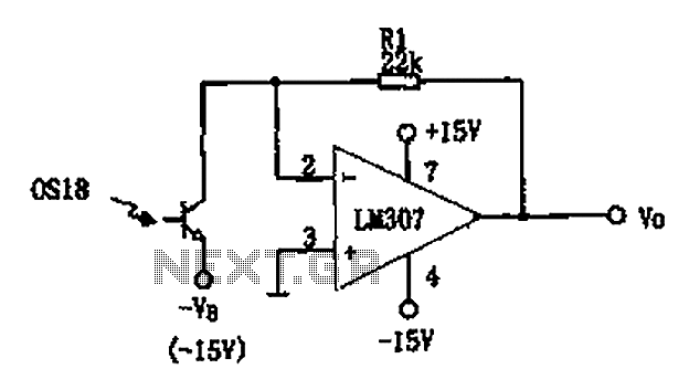
The circuit described is a photoelectric receiver amplifier designed to amplify the electrical signals generated by photodiodes or phototransistors in optoelectronic devices. When the intensity of incident light varies, the photosensitive device generates a corresponding voltage or current. The...
Currently, the most commonly available headphones have an impedance ranging from 2 to 32 ohms. This relatively low value renders them unsuitable for certain designs. However, with some clever modifications, these headphones can be effectively utilized in such applications....

The Mini AV Test Box circuit is designed with simplicity and efficiency in mind. It consists of three main sections, which are clearly delineated in the schematic. The primary components utilized in this circuit include the 7805 voltage regulator,...

The pressure transmitter circuit data acquisition system utilizes the 1B31, an 18-bit A/D converter (AD1170), and an MCS-51 microcontroller. The configuration, as depicted in the accompanying diagram, features a full-scale output voltage of 10 mV from the pressure transmitter...