
Video and DVD Modulator Circuit Electronic Diagram
The video and DVD modulator circuit serves to convert video signals into a format suitable for transmission over VHF or UHF frequencies. This is particularly useful for broadcasting video content to televisions or other receiving devices that operate within these frequency ranges.
The core of the circuit typically includes a high-frequency oscillator, which can be implemented using a transistor. The oscillator generates the carrier wave necessary for modulation. In this setup, the transistor is configured to amplify the input signal and produce a stable output frequency.
The modulation process involves combining the video signal with the carrier wave. This can be achieved through amplitude modulation (AM) or frequency modulation (FM), depending on the design requirements. The modulated signal is then filtered to eliminate unwanted harmonics and noise, ensuring a clean output signal.
Additionally, the circuit may incorporate various components such as capacitors, resistors, and inductors to stabilize the oscillator, control the gain, and manage the frequency response. An output stage may be included to drive the antenna or connect to other transmission media.
Overall, this circuit provides a practical solution for transmitting video content over traditional broadcast frequencies, enabling compatibility with legacy television systems and enhancing the accessibility of video content.The following circuit shows about Video and DVD Modulator in VHF / UHF Circuit Electronic Diagram. Features: oscillator uses a transistor for high .. 🔗 External reference
Related Circuits
Incorporate a straightforward, economical jack-sensing circuit (JACKSENSE) into a DirectDrive automotive headphone amplifier to detect when headphones are plugged into the audio jack. The implementation of a jack-sensing circuit (JACKSENSE) in a DirectDrive automotive headphone amplifier is designed to enhance...
Power an RS232-TTL converter circuit using the serial port to eliminate the need for an external power supply. It has been noted that the DTR, RTS, and TD pins can facilitate this. Since the TD pin is already utilized...
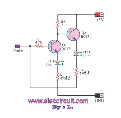
This logic probe circuit is designed for checking voltage levels in TTL circuits. It receives signals from the circuit being tested and indicates whether the logic level is high or low. When the input voltage at the probe tip...
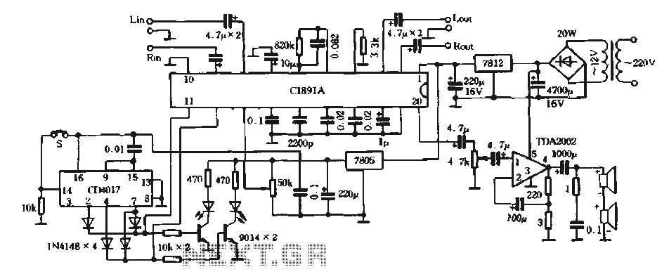
The surround processing section C1891A is a product from Sony Corporation of Japan that features a four-dimensional home theater surround processing circuit. It includes a parent roll phase-shifting circuit and a matrix surround sound amplifier. Additionally, it provides three...
The electronic motor speed controller circuit includes a wireless remote control transmitter circuit and a wireless remote control receiver circuit, as illustrated in the accompanying chart. The wireless remote control transmitter circuit comprises a micro-power wireless remote control transmitter...
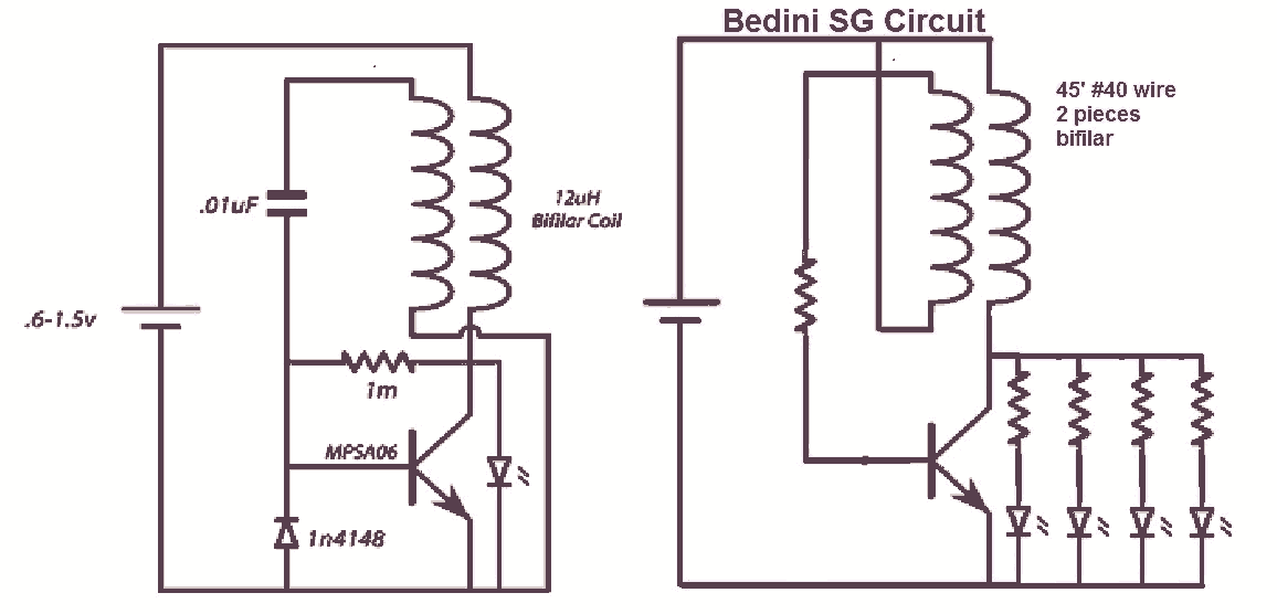
It would be beneficial to obtain schematics of the Joule Thief and Bedini oscillator circuit connections. This is an area that has not been previously explored. The schematic on the left was sourced from the Energetic Forum, while the...