
Mini Logic probe with transistor circuit
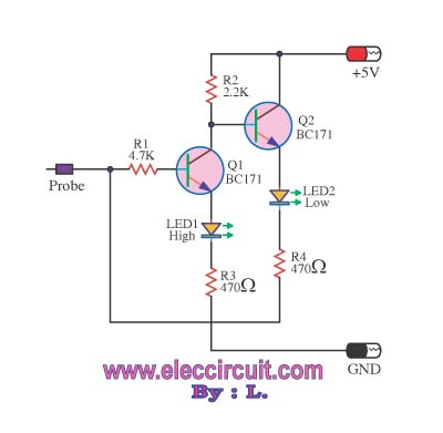
The logic probe circuit operates by utilizing two transistors, Q1 and Q2, along with two LEDs, LED1 and LED2, to visually indicate the logic levels present in a TTL (Transistor-Transistor Logic) circuit. The probe tip is the point of measurement, where the voltage level from the tested circuit is applied.
Transistor Q1 is configured as a switching device that responds to the input voltage. When the input voltage exceeds 2.1 volts, Q1 enters saturation, allowing current to flow through LED1. This LED serves as an indicator for a logic high state, providing a visual cue to the user that the measured voltage is within the expected high range for TTL logic.
On the other hand, when the input voltage is below the threshold, Q1 turns off, and the collector voltage drops. The voltage at the base of transistor Q2, which is connected through resistor R4, also falls below its threshold, causing Q2 to turn off as well. As a result, LED2 does not receive sufficient current to illuminate, indicating a logic low state.
The inclusion of resistors in the circuit ensures proper biasing of the transistors, allowing for accurate detection of logic levels. The design is straightforward yet effective for troubleshooting and testing digital circuits, making it an essential tool for electronics engineers and technicians working with TTL logic systems. Properly calibrated, this logic probe can provide reliable visual feedback on the operational status of digital signals within a circuit.This is a Logic probe circuit is one, That is suitable for checking the voltage levels in the TTL circuit. It receives from the circuit being tested. Shows how high or low logic level one. The circuit when the input voltage to the probe Tip is higher than 2. 1 volts (state logic high ). Transistor Q1 will run the light emitting diodes (LED) LED1 rec eive direct bias will come out shining. Show the logic high (high). When the collector voltage of Q1 running it will fall. and Since the input entered at the end of probe is connected to one end of resistors R4, joint base / emitter of transistor Q2. and Light emitting diode LED2 will get back to bias Q2 and LED2 does not work. 🔗 External reference
Related Circuits
This simple circuit is started running by connecting a twelve volt battery across the terminals, causing the large diameter Light-Emitting Diode to light up. When the battery is removed, the LED stays lit up because the circuit has become...
The objective is to enhance information transmission by utilizing articles. Please contact us via email at [email protected] within 15 days if there are issues related to article content, copyright, or other concerns. Prompt action will be taken to resolve...
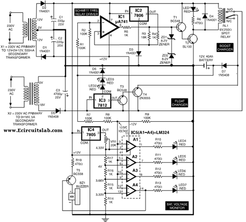
This circuit illustrates the use of the 7806 IC in an automatic battery charger circuit diagram. It is designed for a car battery with an approximate rating of 40 Ah. The automatic battery charger circuit utilizing the 7806 integrated circuit...

A field strength meter utilizing a biased Schottky detector employs a temperature-compensated Schottky diode within an amplified, untuned field strength indicator powered by two AA cells. This device indicates the relative field strength of RF fields ranging from a...
If a negative supply is required for an operational amplifier or if a negative bias voltage is needed while operating from a single supply voltage, such as in battery applications. To generate a negative supply voltage from a single positive...
This is a portable, high-power incandescent electric lamp flasher. It functions as a dual flasher (alternating blinker) capable of managing two independent 230V AC loads (bulbs L1 and L2). The circuit is entirely transistorized and operates on battery power....
Warning: include(partials/cookie-banner.php): Failed to open stream: Permission denied in /var/www/html/nextgr/view-circuit.php on line 713
Warning: include(): Failed opening 'partials/cookie-banner.php' for inclusion (include_path='.:/usr/share/php') in /var/www/html/nextgr/view-circuit.php on line 713