
Video distribution amplifier
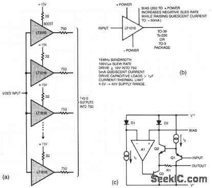
The circuit design incorporates resistors in the output lines primarily to mitigate signal reflections that can occur in unterminated transmission lines. This is crucial in high-frequency applications where impedance mismatches can lead to significant signal integrity issues. The use of resistors aids in damping these reflections, ensuring that the transmitted signal maintains its integrity over distance.
In scenarios where the characteristics of the transmission line are well understood, the output resistors may be omitted, allowing for a more straightforward circuit design without compromising performance. However, careful consideration must be given to the potential for reflections if the line is not properly terminated.
To comply with NTSC (National Television System Committee) gain-phase specifications, a small-value boost resistor is integrated into the circuit. This component is essential for maintaining the required signal levels and phase relationships, which are critical for proper video signal transmission.
The LT1010 operational amplifier is referenced in the context of this design, with Figures 3-27B and 3-27C providing graphical representations of its characteristics. The LT1010 is known for its high-speed performance and low distortion, making it suitable for applications requiring precise signal processing. Understanding its characteristics is vital for optimizing the overall circuit performance, particularly in video signal applications where fidelity is paramount.The resistors in the output lines are included to isolate reflections from unterminated lines. If the line characteristics are known, the resistors can be deleted. To meet NTSC gain-phase requirements, a small-value boost resistor is used. Figures 3-27B and 3-27C show the LT1010 characteristics. 🔗 External reference
Related Circuits
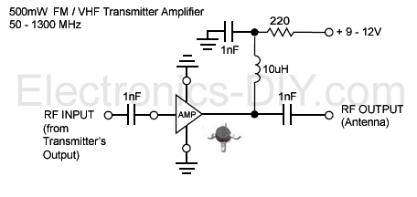
This is an aerial achievement low noise 500mW amplifier/booster designed for low power FM transmitters such as BA1404, BH1417, BH1415, and 433MHz transmitter modules. The amplifier utilizes a chip that incorporates various transistor stages and all necessary components within...
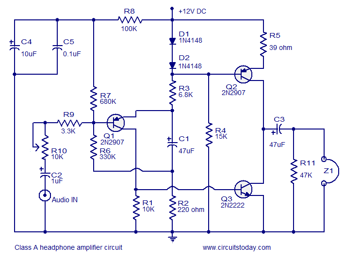
Transistor amplifier circuits that are simple and easy to construct. This includes a headphone amplifier, a four-transistor amplifier, and a low-power amplifier. Transistor amplifier circuits are fundamental components in electronic design, offering various applications ranging from audio amplification to signal...
These are circuits of high impedance low capacitance buffer and high impedance low capacitance amplifier. The first figure is a high impedance low capacitance. High impedance low capacitance circuits are critical in various electronic applications, particularly in signal processing and...
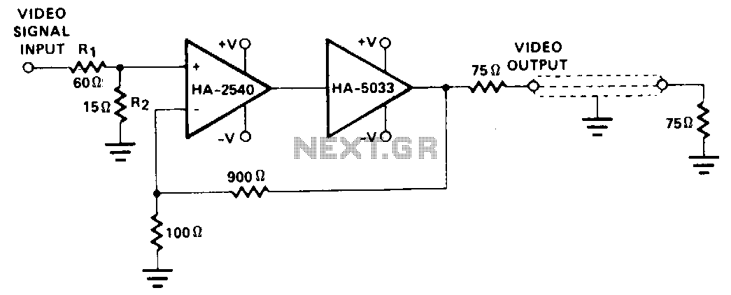
This configuration employs the wide bandwidth and high speed of the HA-2540, in conjunction with the output capabilities of the HA-5033. Stabilization circuitry is not implemented, as the HA-2540 operates at a closed-loop gain of 10 while maintaining an...
This low-noise microphone amplifier is built with the MAT02 produced by PMI. This microphone amplifier is highly efficient and features a very low noise level. The amplification can be set to either 20 dB or 23.5 dB (10x or...
The TDA2040 is a monolithic integrated circuit housed in a Pentawatt package, designed for use as an audio class AB amplifier. It typically delivers an output power of 22W (with a distortion factor of 0.5%) at a supply voltage...
Warning: include(partials/cookie-banner.php): Failed to open stream: Permission denied in /var/www/html/nextgr/view-circuit.php on line 713
Warning: include(): Failed opening 'partials/cookie-banner.php' for inclusion (include_path='.:/usr/share/php') in /var/www/html/nextgr/view-circuit.php on line 713