
Video monitor adapter enhances oscilloscope
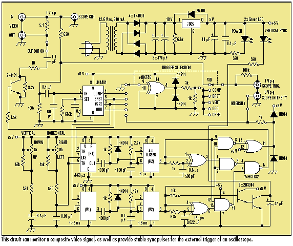
The circuit design effectively addresses the challenges associated with displaying video signals on oscilloscopes by utilizing a combination of sync detection and timing mechanisms. The LM1881 Sync Detector plays a crucial role in isolating the sync pulses necessary for accurate triggering, ensuring that the oscilloscope can maintain a stable display even when faced with the complexities of composite video signals. The dual timer configuration, utilizing 555 timers, allows for precise control over the dimensions and positioning of the cursor, providing users with the flexibility to inspect specific areas of the video signal in detail.
The integration of the 74HCT86 exclusive-OR gate and the 74HCT132 NAND gates further enhances the functionality of the circuit, allowing for the creation of a well-defined square cursor that can be easily manipulated across the display. The use of transistors for signal modulation ensures that the video output is not only visually informative but also maintains the integrity of the original signal. The design's consideration for component tolerances and the inclusion of protective elements, such as the capacitor, reflects a thorough understanding of the practical challenges encountered in electronic circuit design. Overall, this circuit serves as an invaluable tool for professionals engaged in video signal analysis and editing, facilitating enhanced precision and control in oscilloscope applications.Video signals can be difficult to display on an oscilloscope. Normal trigger circuits in most oscilloscopes have trouble getting a stable trigger from the combined vertical and horizontal sync signals, color burst, and picture signal in a composite video waveform. Even the TV Sync trigger detector available in some low-cost oscilloscopes is inadequate to obtain a
stable display. The circuit shown monitors a composite video signal and provides stable sync pulses for the external trigger of an oscilloscope (see the figure). The Trigger Selector switch chooses Video, Composite Sync, Color Burst Sync, Vertical Sync, Vertical Odd Field Sync, or Cursor Position for the oscilloscope.
Two timer chains provide a rectangular cursor (width and height approximately 8% of the full screen). The cursor is movable across the full width and height of the screen by adjusting the Horizontal and Vertical Cursor Controls.
The circuit provides a positive Intensity pulse for the oscilloscope Intensity (Z-axis) input. This permits close inspection of any portion of the video signal corresponding to the position of the cursor. If the oscilloscope is hooked up to a color demodulator as a vectorscope, this feature highlights the demodulated color on the vectorscope display.
This is useful in applying color correction or enhancement as part of a video-editing setup. The circuit contains a Power LED and a Vertical Sync Indicator LED. The Cursor On switch allows the movable cursor to be observed on a video monitor attached to the Video Out connector. The Intensity switch controls the Intensity pulse to the oscilloscope. The LM1881 Sync Detector separates the various sync signals from the composite video into stable logic pulses.
Color burst sync, which occurs at the start of every horizontal line, is applied to a 555 CMOS timer. The timer output pulse width is adjusted by the Horizontal Cursor Control over the full width of the line.
This output pulse drives a second 555 timer which establishes the cursor window width. The output of this second timer drives a 74HCT86 exclusive-OR gate through an RC circuit, providing a short positive pulse corresponding to the start and end of the horizontal cursor window. Vertical sync, which occurs at the start of every vertical field, is similarly processed by a parallel set of timer circuits to establish the start and end of the vertical cursor window.
The 74HCT132 NAND gates combine these signals into the desired square cursor. The resulting square cursor drives the 2N4401 transistor. When switched on, the transistor reduces the amplitude of the video signal at the Video Out connector through the voltage-divider action of the 5. 1- © and 10- © resistors. This results in a gray cursor surrounding the area of interest on a video monitor. The 0. 1- µF capacitor protects the transistor from any dc voltage on the video. The fixed resistors associated with the Horizontal and Vertical Cursor Controls provide the range of timing adjustments shown.
Their values may be modified to account for tolerances of the other components. 🔗 External reference
Related Circuits
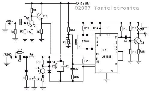
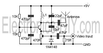
This small circuit transmitter processes audio signals from a sound table or microphone, as well as video signals from a camera, DVD, or video cassette. It has a composite video output, allowing direct transmission from a computer over a...

This page describes a cheap and simple yet flexible HDMI to parallel 3.3V interface. This allows connecting most LCD frames to the BeagleBoard without any further interface required. It is used with some 7-inch 800x480 displays running Angstrom Linux...
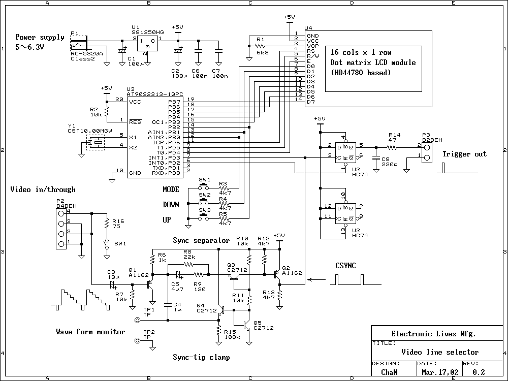
When measuring video signals with an oscilloscope, a video line selector is very useful to find a scan line. The line selector generates a trigger pulse at the selected line; the oscilloscope will display only the selected line. This...
To transmit video and audio signals to multiple televisions simultaneously, a video amplifier splitter utilizing a transistor can be employed. A video amplifier splitter is an electronic device designed to distribute a single video and audio signal to multiple output...
This is a simple video transmitter capable of transmitting signals up to 50 meters. It can be utilized with cameras or other video sources and allows viewing on VHF channel analog televisions. The video transmitter operates on a supply...
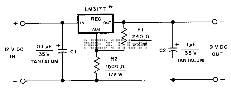
This adapter provides a regulated 9-V source for operating a Kenwood TR-2500 hand-held transceiver in a vehicle. The mounting tab of the LM317T is electrically connected to its output pin, which should be considered during the construction of the...