
Circuit Power transmitter of communitarian wireless TV lm1889 audio and video
The circuit design emphasizes simplicity and efficiency in transmitting audio and video signals. The use of the LM1889N integrated circuit allows for reliable modulation and signal processing, making it suitable for various applications such as community broadcasting and surveillance. The circuit's ability to transmit over a distance of up to 500 meters is advantageous for urban environments where line-of-sight may be obstructed. The careful selection of components, including the coils and resistors, ensures optimal performance and minimizes the risk of interference. The design also considers the importance of power supply quality, as fluctuations can significantly impact the transmitted signal quality. Overall, this circuit presents a practical solution for those interested in setting up a low-power video and audio transmission system.This small circuit transmitter processes the signs of audio of a sound table or microphone, and the signs of video of a camera, or still the audio signs and video of a DVD, Video-cassette or even it sweats her video plate has an exit of composed video, you can transmit direct of your computer. Playing them in a channel free from the strip of VHF. These signs can be irradiated with a common antenna and captured in an it distances of until about 500 meters that it is the most appropriate for urban areas, reminding that and necessary to be a lot of caution and careful for not interfering in frequencies of other issuing, as well as to emergency services. Depending on the local conditions (existence or not of obstacles). Fed with tensions from 12 to 15 Volts, the circuit has excellent I carry out so much in the emission of monochrome signs, as in colors.
An important point of this project the easiness with that he can be set up and adjusted, since only two coils are used. Ideal to be used with surveillance cameras turning the without thread. The heart of this circuit transmitter is the integrated circuit LM1889N of National Semiconductor, that consists of a Modulator of Video for TV in an involucres of 18 pins DIL.
This integrated circuit used in videocassettes and videogames, exactly to process the image information and sound, so that they can be played in a channel free from the strip of VHF. As it is component that used in commercial equipments, besides the reliability, we have a certain obtaining easiness.
The readers, with luck, until they can find this available component in an old videogame that it is out of use, and you take advantage of it to set up your station communitarian. count all the necessary stages to the processing of the video signals and audio of a transmitter of signs of TV.
The coil L1 together with the capacitor in parallel, it generates the sign of 4, 5 MHz that, modulated with the sound, it should be separate from the bearer of video of this frequency. Like this, the adjustment that should do in this coil it simply consists in you take it to 4, 5 MHz, in way we obtain it sound.
The audio modulation done by a varicap in a very simple way, so that the intensity of the audio sign obtained in most of the exits of the sound table it should provide a good reproduction. The video sign, that obtained of the video exit of any camera, videocassette, DVD, applied in the pin 13 of the circuit integrated after going by an amplification stage with two transistors.
We should adjust the frequency of this oscillator for the channel free from the strip of VHF, usually a channel baixo(2 to 6) in that the broadcasting station will operate. The exit of RF, obtained in the pin 11 mischievous to an amplifying stage with a transistor and of this for the antenna expresses or a telescopic antenna, in case the transmission is of short reach.
Observe that in the modulation of audio of this circuit, the sign generates two subportator being below a 4, 5 MHz above the frequency of the channel and other 4, 5 MHz. As one of them not eliminated, she can cause interferences in the adjacent channel. That means that you should choose a free channel in your place, but that doesn`t have adjacent channels operating.
The power supply of the circuit can be made with tensions of 12 (7812) or 15(7815) Volts of a source with at least 1A and excellent filter. A deficient filter in this type of so much circuit can provoke snores in the sound, as undulations in the image.
The healthy resistors of 1/8W or larger. The power source so much can be the one of 12V/1A, as it can be made a modification to operate with 15V, being enough for that to change the transformer and the integrated circuit. The circuit plate printed for the assembly shown below in the illustration. The coils, as always, are the elements more critics of the project. L1 formed by 40 you exhale of thread enameled fine (30 to 34 🔗 External reference
Related Circuits
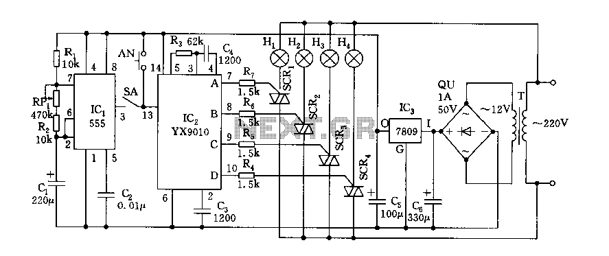
Fantasy lights offer wonderful changes suitable for storage, dance halls, or family holiday decorations. The control circuit is depicted here, which includes a multivibrator control circuit, a thyristor trigger circuit, and a step-down power supply circuit. The AC step-down...
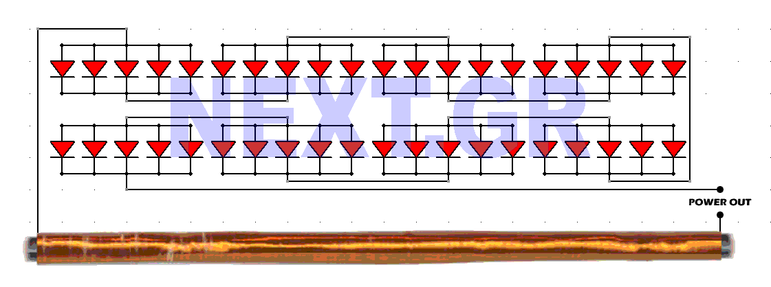
This schematic converts surrounding radio waves into usable electrical current. The power levels can be increased by incorporating additional diodes. The key factors in this device are the type of diodes used and the construction of the antenna. The...
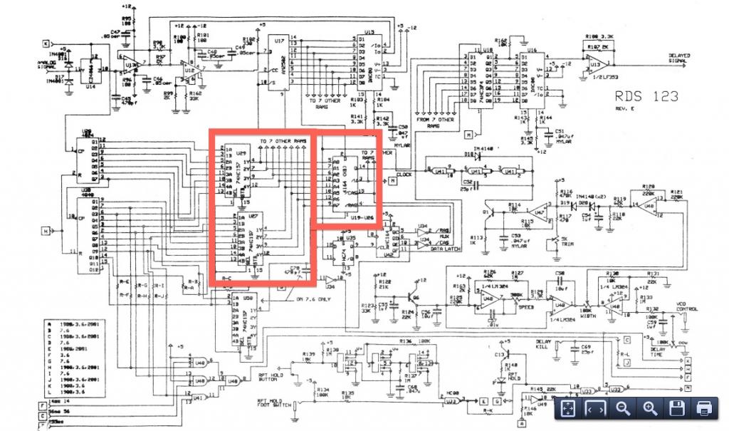
The TEA5764UK is a single-chip, electronically tuned FM stereo radio that includes a Radio Data System (RDS) and Radio Broadcast Data System (RBDS) demodulator, along with an RDS/RBDS decoder. This device is designed for portable applications and features fully...
This project is suitable for individuals who enjoy experimenting with electronics. It presents a low risk of damaging the unit. This project involves creating a simple electronic circuit that allows users to engage in hands-on experimentation without significant risk. The...
This is a police tone circuit for a siren. It is simple and easy to construct. VR1 and VR2 are used to adjust the delay of the siren sound. The design is straightforward and uncomplicated. The police tone siren circuit...
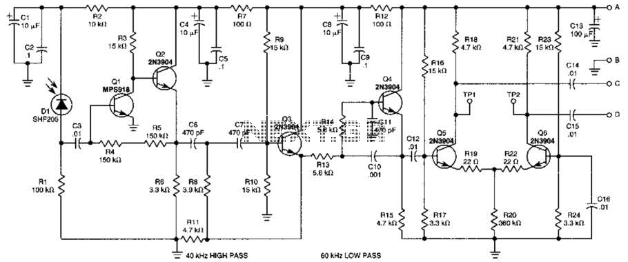
This receiver is designed to detect infrared (IR) or light beams that are frequency modulated on a 50-kHz carrier. The transistors Q2, Q1, Q3, and Q4 form an active filter and amplifier, while the differential amplifier formed by Q5...
Warning: include(partials/cookie-banner.php): Failed to open stream: Permission denied in /var/www/html/nextgr/view-circuit.php on line 713
Warning: include(): Failed opening 'partials/cookie-banner.php' for inclusion (include_path='.:/usr/share/php') in /var/www/html/nextgr/view-circuit.php on line 713