
Video Signal Carrier Circuit
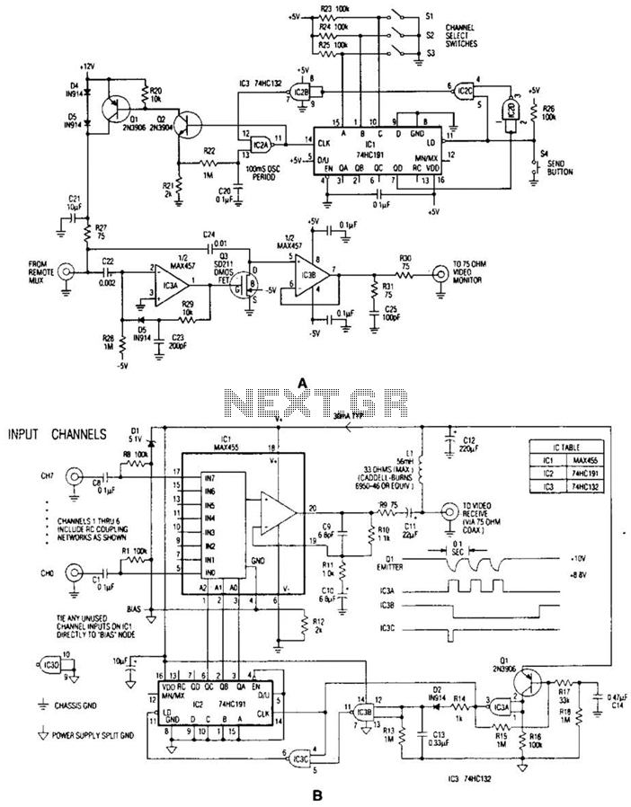
The video system described employs a coaxial cable as a multifunctional medium, enabling both power supply and video signal transmission. The multiplexer box (A) integrates an 8-channel multiplexer and an amplifier (IC1) that are essential for managing multiple video signals. The coupling capacitor (C1) is critical for ensuring that the baseband video signal is effectively transmitted over the coaxial cable without interference from the DC power. The inductor (L1) serves to isolate the video signal from the DC power line, preventing any potential disruptions that could arise from shared pathways.
Within the interface box (B), the channel selection mechanism operates through a binary encoding system, utilizing three bits to represent eight possible channels. This encoding can be accomplished through physical switches or by an external digital input, providing flexibility in operation. The momentary activation of the send button initiates a sequence that involves the downconverter IC1 and the gated oscillator IC2A. This sequence is crucial for generating a channel-selection burst, which ensures that the correct video channel is selected and displayed.
The design of this system emphasizes efficiency and reliability, particularly in environments where remote surveillance is necessary. The coaxial cable's dual function minimizes the need for additional wiring, reducing installation complexity and potential points of failure. Overall, this video system exemplifies an effective integration of signal processing and power distribution, suitable for various surveillance applications. In the video system of Figs. A and R, a single coaxial cable carries power to the remote location, selects one of eight video channels, and returns the selected signal. The system can choose one of several remote surveillance-camera signals, for example, and display the picture on a monitor near the interface box.
The heart of the multiplexer box (A) is a combination 8-channel multiplexer and amplifier (IC1). Cll couples the multiplexer`s baseband video output to the coax, and LI decouples the video from dc power arriving on the same line, This powerapproximately 30 mA at 10 Vsupplies all circuitry in the multiplexer box. In interface box (B), a desired channel is encoded by three bits, set either by switches as shown or by an applied digital input. Momentary depression of the send button triggers downconverter IC1 and gated oscillator IC2A to initiate a channel-selection burst,
🔗 External reference
Related Circuits
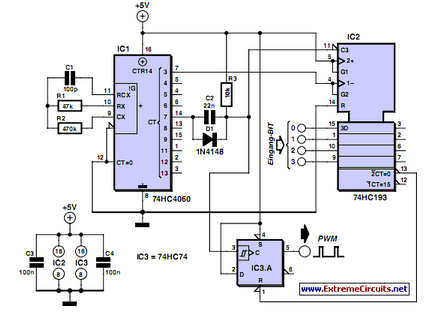
PWM waveforms are frequently utilized to regulate the speed of DC motors. The duty cycle of the digital waveform can be defined using an adjustable parameter. PWM (Pulse Width Modulation) is a technique employed to control the power delivered to...
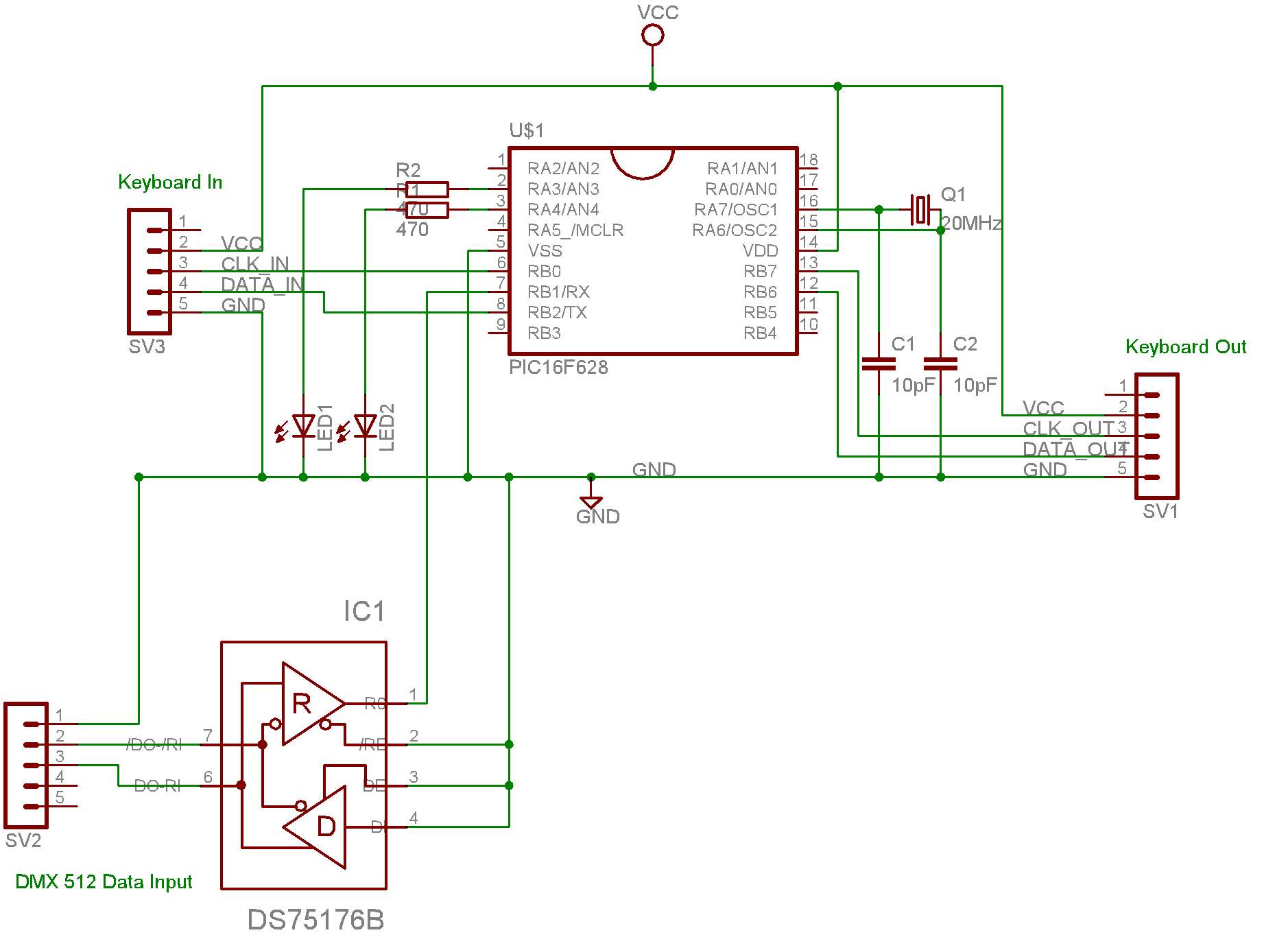
This system is designed for use with a PC connected to video projectors, enabling a lighting controller to manage a presentation displayed on the video screen. The PC used for the presentation is situated in a different location from...
This circuit is similar to the previous one but employs positive feedback to enhance the amplitude delivered to the speaker. It was adapted from a small five-transistor radio that utilizes a 25-ohm speaker. In the prior circuit, the load...
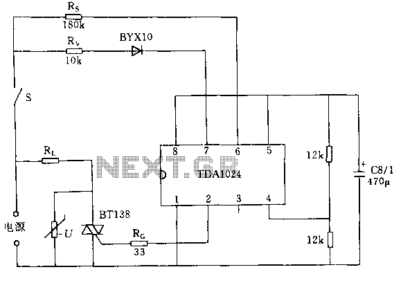
The circuit switch S closes when the integrated circuit TDA1024 is activated. A trigger pulse is generated by the zero crossing of the mains voltage, allowing a bidirectional thyristor to conduct full current through the load Rl. When switch...
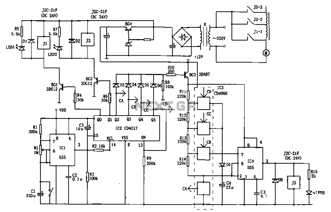
The AC welder operates intermittently, with power consumption during these periods reaching several hundred watts. The AC welder saving controller circuit enables the welding machine to automatically cut off power during no-load conditions while also automatically restoring power for...
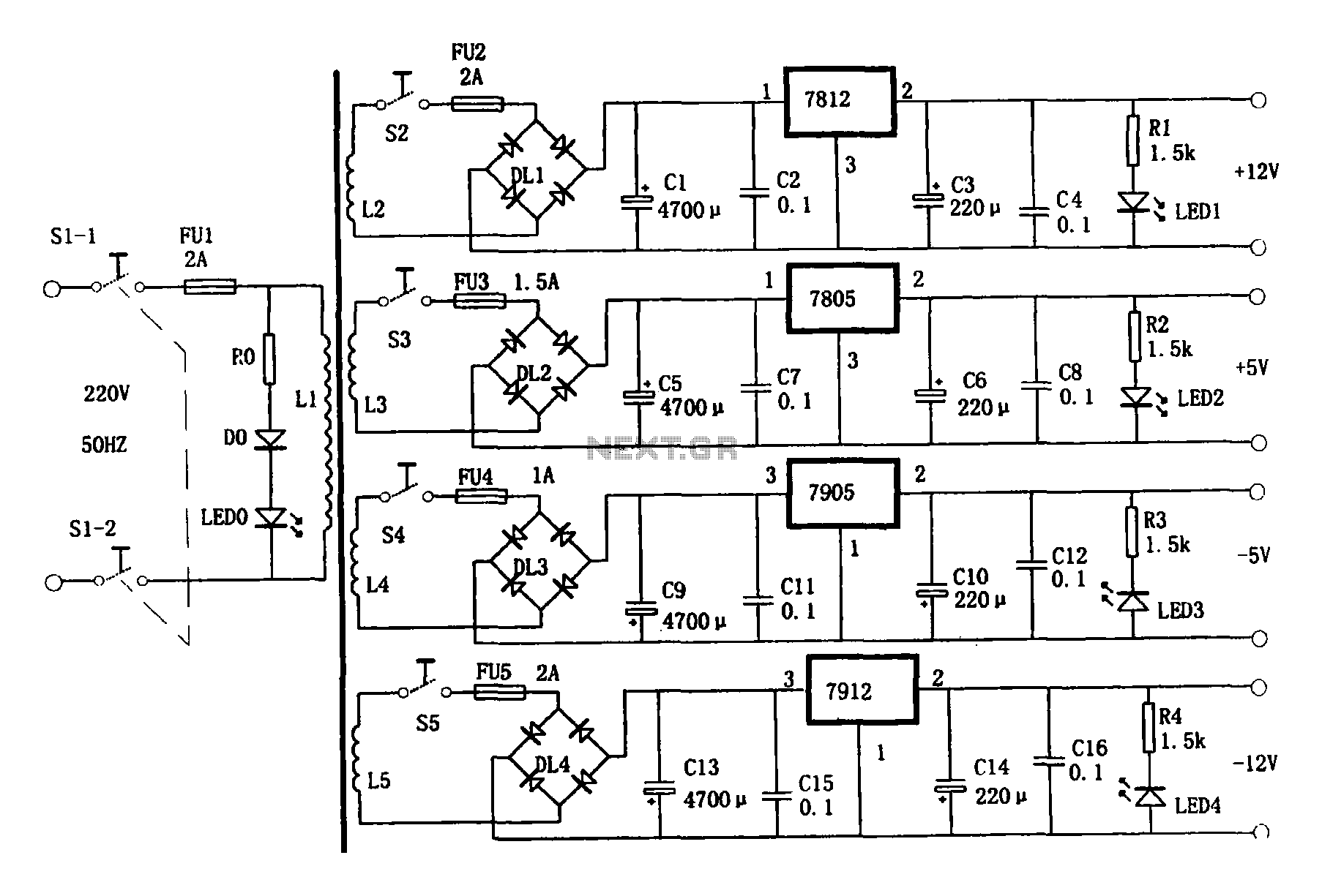
This document presents a multi-output power supply circuit. The circuit utilizes the secondary winding of a transformer and incorporates four voltage regulators: 7812, 7805, 7905, and 7912, providing independent output voltages of +12V, +5V, -5V, and -12V, respectively. Each...
Warning: include(partials/cookie-banner.php): Failed to open stream: Permission denied in /var/www/html/nextgr/view-circuit.php on line 713
Warning: include(): Failed opening 'partials/cookie-banner.php' for inclusion (include_path='.:/usr/share/php') in /var/www/html/nextgr/view-circuit.php on line 713