
Improved 3 Transistor Audio Amp (80 milliwatt) circuit
This circuit utilizes positive feedback to improve speaker amplitude, enhancing performance over previous designs. The configuration addresses the limitations of direct connection to the positive supply by incorporating a feedback mechanism that allows for greater voltage swings. The use of a 1k-ohm load resistor connected to the speaker plays a critical role in modulating the transistor operation, ensuring that the upper NPN transistor can be effectively turned off when the output is negative. The inclusion of a 470 µF capacitor is vital, as it provides the necessary charge to assist in turning on the upper NPN transistor during positive swings, which is essential for maximizing output power.
The choice of diodes instead of a resistor for biasing allows the circuit to operate efficiently at lower voltages, thus reducing distortion and improving audio quality. The specified transistors, while effective, can be substituted with smaller alternatives that meet the current handling requirements. It is crucial to monitor the idle current to maintain proper operation and prevent overheating, particularly under load conditions. The circuit's compatibility with an 8-ohm speaker allows for versatility in application, although careful consideration should be given to the output power levels.
For optimal performance, tuning the resistor value to achieve a balanced output voltage is advisable. This adjustment can significantly influence the overall gain and efficiency of the circuit, ensuring that the amplifier operates within desired parameters while maximizing audio fidelity. The design illustrates a practical approach to enhancing audio output in compact electronic devices, making it suitable for various applications in consumer electronics.This circuit is similar to the one above but uses positive feedback to get a little more amplitude to the speaker. I copied it from a small 5 transistor radio that uses a 25 ohm speaker. In the circuit above, the load resistor for the driver transistor is tied directly to the + supply. This has a disadvantage in that as the output moves positive, the drop across the 470 ohm resistor decreases which reduces the base current to the top NPN transistor. Thus the output cannot move all the way to the + supply because there wouldn`t be any voltage across the 470 resistor and no base current to the NPN transistor.
This circuit corrects the problem somewhat and allows a larger voltage swing and probably more output power, but I don`t know how much without doing a lot of testing. The output still won`t move more than a couple volts using small transistors since the peak current won`t be more than 100mA or so into a 25 ohm load.
But it`s an improvement over the other circuit above. In this circuit, the 1K load resistor is tied to the speaker so that as the output moves negative, the voltage on the 1K resistor is reduced, which aids in turning off the top NPN transistor. When the output moves positive, the charge on the 470uF capacitor aids in turning on the top NPN transistor.
The original circuit in the radio used a 300 ohm resistor where the 2 diodes are shown but I changed the resistor to 2 diodes so the amp would operate on lower voltages with less distortion. The transistors shown 2n3053 and 2n2905 are just parts I used for the other circuit above and could be smaller types.
Most any small transistors can be used, but they should be capable of 100mA or more current. A 2N3904 or 2N3906 are probably a little small, but would work at low volume. The 2 diodes generate a fairly constant bias voltage as the battery drains and reduces crossover distortion. But you should take care to insure the idle current is around 10 to 20 milliamps with no signal and the output transistors do not get hot under load.
The circuit should work with a regular 8 ohm speaker, but the output power may be somewhat less. To optimize the operation, select a resistor where the 100K is shown to set the output voltage at 1/2 the supply voltage (4. 5 volts). This resistor might be anything from 50K to 700K depending on the gain of the transistor used where the 3904 is shown.
🔗 External reference
Related Circuits
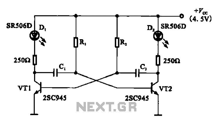
The multivibrator flashing light emitting diode (LED) display driver circuit can be utilized in toys, creating flashing effects in the eyes of animals or monsters. This circuit employs a multivibrator configuration, typically a 555 timer IC or a similar component,...

A digital stopwatch or digital timer circuit schematic is constructed using the timer IC LM555 and the 4-digit counter IC MM74C926, which is paired with a multiplexed 7-segment LED display. The digital stopwatch circuit utilizes the LM555 timer IC configured...
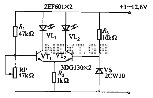
When the battery voltage is within the range of 7 to 12.6V, the light-emitting diode VLi illuminates, maintaining a consistent brightness. If the battery voltage drops below 7V, VLi begins to emit a red light, and the brightness of...
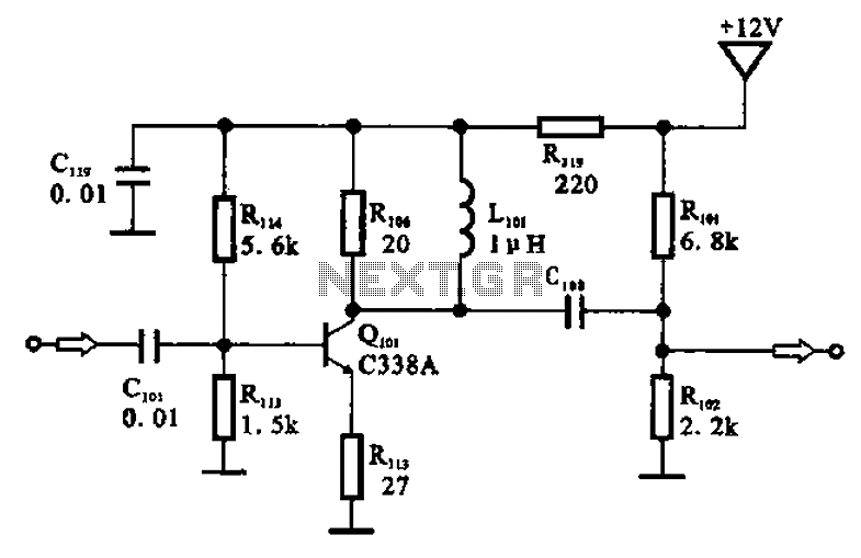
The amplifier circuit is designed as a pre-amplifier configuration. It utilizes transistor Q101 and other components such as inductor L101 and biasing elements. The transistor operates as a common emitter intermediate frequency (IF) amplifier. The IF signal is coupled...
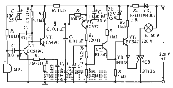
The circuit utilizes condenser microphones to detect sound and convert it into signal variations. This signal is then processed through directly coupled transistors VT1 and VT2, which form an amplification stage before being fed into a switching circuit. The...
This device is designed for individuals seeking to achieve a tan while minimizing excessive exposure to sunlight. It utilizes electrolytic capacitors as one of its components. The tanning device operates by utilizing a controlled exposure mechanism that regulates the intensity...
Warning: include(partials/cookie-banner.php): Failed to open stream: Permission denied in /var/www/html/nextgr/view-circuit.php on line 713
Warning: include(): Failed opening 'partials/cookie-banner.php' for inclusion (include_path='.:/usr/share/php') in /var/www/html/nextgr/view-circuit.php on line 713