
Voltage Controlled Switch

The proposed circuit functions as a voltage limiter and charging controller, ideal for solar applications. The core of the design involves a comparator circuit that monitors the voltage level and controls an LED indicator based on the voltage threshold set by zener diodes. The use of a 5V zener diode and a 3V zener diode effectively creates a reference voltage of approximately 8V. This threshold can be adjusted by modifying the zener diodes used or by changing the resistor values in the voltage divider.
The circuit can be powered by two 9V batteries, which introduces variability in voltage levels. The comparator's output is connected to the LED, which illuminates when the input voltage exceeds the set threshold. If the voltage falls below this threshold, the LED turns off. The circuit's behavior can be reversed by swapping the comparator's input leads, allowing for flexibility in design based on specific application needs.
For scenarios involving low input voltages (between 1V and 2.4V), a more complex arrangement is required. A capacitor charging circuit can be implemented, where a capacitor is charged until it reaches 2.4V, at which point a switch closes, illuminating an LED. Simultaneously, another capacitor can be charged while the first one discharges. This requires careful selection of components to ensure that the op-amp operates within its required voltage range, as most op-amps necessitate a minimum voltage of around 3V.
To control a relay with the desired voltage thresholds, the circuit can be simplified using a diode and a voltage divider in conjunction with an op-amp. The op-amp can be configured to activate the relay at 5V by connecting the appropriate pins to the voltage divider output. If the intention is to have the relay disengage at voltages below 5V, the connections to the comparator inputs must be swapped.
In summary, this circuit design combines charging control with voltage limiting functionalities, adaptable for solar applications. Careful attention must be paid to component selection and configuration to ensure reliable operation across the specified voltage ranges. Schematic diagrams should be developed to illustrate the connections clearly, aiding in the assembly and troubleshooting of the circuit.This is a little circuit that i designed that could be used for achargingcontroller or voltage limiter. Its very useful if you are thinking of maki. In the assembly of the circuit u can alter the circuit as you please. For instance ididn`tgo as exact as theschematic. Just follow the diagram belo. In the circuit that i build thatsnottotally the same as the in the diagram, is suppose to turn on the led at 8V because i used a 5v and 3v zener. I. If turn the comparatorpositiveand negative leads around will have the reverseeffect. Imeaninstead of turning on at 8V it will turn off and any. This is a little circuit that i designed that could be used for achargingcontroller or voltage limiter. Its very useful if you are thinking of making a solarcharger. In the circuit that i build thatsnottotally the same as the in the diagram, is suppose to turn on the led at 8V because i used a 5v and 3v zener.
I also used a two 9 Vbatteries which voltages differ. The circuit i suppose to turn the led on at 8 V and any voltage lower than it should go off. If turn the comparatorpositiveand negative leads around will have the reverseeffect. Imeaninstead of turning on at 8V it will turn off and any voltage thats lower than that it will be on. Sorry idon`thave a picture of that particular instance, but i will put in one any way. [ for decorative purposes] I did not understand which component you used and why the 5V supply Can`t we use a comparator that derives the required power from the charge capacitor Will you please explain so that it`ll be easy for me to make this circuit.
Please help. Thank u for the reply. The problem is that the solar panel I am using only give 1. 5 V output. So I think may be I need to use some sort of amplifier because I can not use any external power supply. And why do we need bi-stable multivibrator Please help me by drawing up a schematic that works for me.
It would be a great help. I need to make a circuit working between 1 V and 2. 4 V. I want to make a solar charger that charges a capacitor until it reaches 2. 4 V, once the voltage reach 2. 4 V, the switch is closed and the led lits up. At the time, 1st capacitor is discharging, I want to charge another capacitor. When the 1st capacitor discharges to 1 V, then I want to charge the 1st capacitor again and connect the load to 2nd capacitor. Please help me with this. I`ll be very thankful to you. the problem i see with this is that most opamps need @ least 3v to work properly. so you may have to run an external power supply or a larger voltage solar panel to power the opamp the rest is easy.
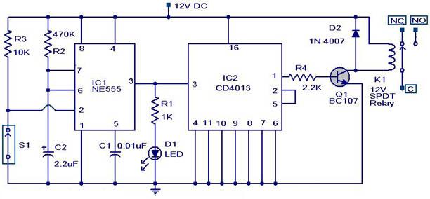
i draw up a schematic for you. THanks for posting this, right along the lines of what I am looking for. What would I need to change to be able to control a realy with this circuit. Specifically, have a SPST relay engange at 5V or higher, or relay disengage at anything under 5 volts Any help is appreciated. hi crinton, sorry i didnt update this thing yet but there is an easier way of doing it. You can use one diode and a voltage divider plus an opamp / comparator. Ive placed a schematic on below it will show you how to connect it. The circuit is currently connected to turn on @ 5V, if you want it to do the opposite turn off @ 5V exchange the positions of pin 2 and 3.
i hope you know how to use a transistor. I labeled ther transistor points B for base, C for collector and E for Emitter. Just purchase any npn low powered npn transistor and you will be fine. Transistors come in 3 different pin configurations CBE, BCE, ECB. the package will show you the pin out. if not go and reference it online. if i missed any thing message me back. this is a very nice I thanks i dont understand it all but im going to collage and will ask some friends to help me out wonderful place for me to start though thanks. Hey, I like the idea, I am looking to find specific answers for a particular setup I am trying to put together.
Could you help me ju 🔗 External reference
Related Circuits
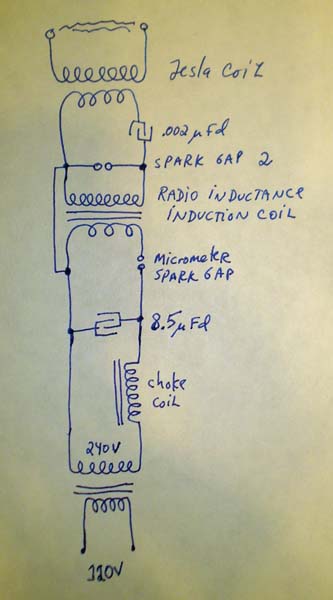
Many individuals assume that spark gap Tesla coils require high voltages, typically ranging from 4 kV to 15 kV or more. However, some interesting experiments can be conducted using as little as 240 V directly. Aside from very low...
An LMX1601 Phase locked loop, a discreet FET VCO, and an AVR microcontroller combine to make a stable, easy to use monophonic FM transmitter that includes an audio activated switch that turns the transmitter on only when it is...
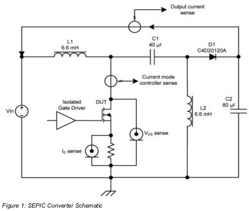
Comparing the performance of 1200V silicon carbide (SiC) MOSFETs with 1200V silicon MOSFETs and IGBTs at high frequency is essential to identify the differences in device losses and power-handling capabilities among these technologies. A demonstration platform has been developed...

The title of this article raises the question of why the extensive selection of fully integrated voltage regulators should be supplemented with a version built using discrete components. Specifically, what advantages does this circuit provide that the well-known three-terminal...
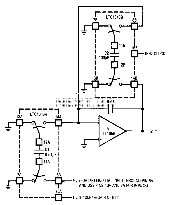
The circuit utilizes the LTC1043 in a variable gain amplifier configuration, which offers continuously adjustable gain, gain stability of 20 ppm/°C, and supports both single-ended and differential inputs. Two separate LTC1043 devices are employed in the design. The LTC1043B...
A magnetic switch is a circuit designed to respond to surrounding magnetic fields detected by the sensor. This series of magnetic switches employs limit switch sensors that include an additional metal plate capable of responding to a magnet. The...