
VU-meter
The circuit design features a quad comparator configuration using LM339 devices, which are instrumental in achieving the desired performance of the VU meter. The incorporation of a flyback DC converter facilitates efficient power management, while the buck and step-up converters ensure that the circuit operates within the required voltage ranges.
The VU meter's design emphasizes a logarithmic response to accurately reflect audio levels, which is critical for professional audio applications. Each of the 40 LEDs per channel is driven by a comparator, with reference voltages established through a resistor network. This allows for precise control over the LED illumination corresponding to audio levels, enhancing the visibility and functionality of the meter.
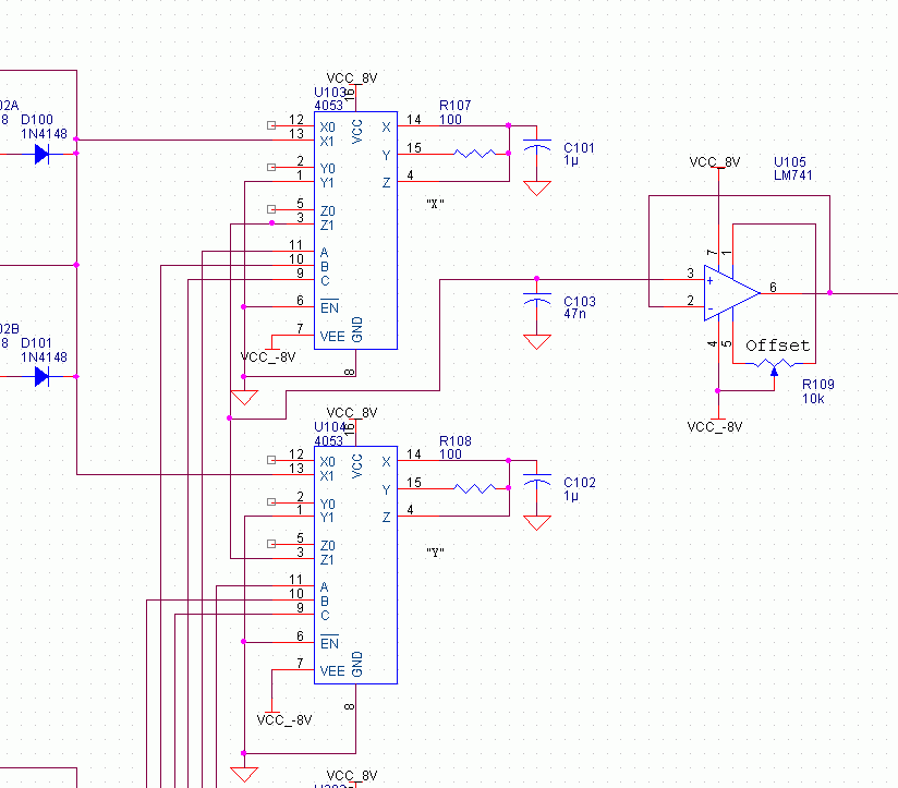
The input stage of the circuit employs ideal rectification to convert the AC audio signal into a DC level suitable for processing. The subsequent RC smoothing circuit is designed to filter out high-frequency noise, ensuring that the VU meter responds accurately to the audio signal's dynamics. However, the challenge of slow decay times after transients necessitates the implementation of a sample-and-hold circuit. This circuit architecture enables the capture of peak audio levels, with the first capacitor storing the peak value while the second capacitor displays this value on the LED bar.
To ensure that no peaks are missed during the discharge of the first capacitor, a second sample-and-hold circuit is synchronized with the first. This dual-sample-and-hold configuration guarantees continuous monitoring of audio peaks, providing a real-time display that accurately reflects the input signal's characteristics.
The timing and control of the sample-and-hold circuits are managed by a 555 timer in conjunction with 4000-series CMOS logic, allowing for flexible adjustments to the sampling rate. This adaptability is crucial for tailoring the VU meter's response to different audio signals.
The power supply design is critical for the overall functionality of the circuit. The dual-sided operating voltages of +/- 8 V provide the necessary headroom for the op-amps and comparators, ensuring optimal performance while minimizing heat generation. The choice of a 7808 voltage regulator, paired with a heatsink, supports the current requirements for the LED displays, while the charge pump and 7908 regulator efficiently generate the negative voltage rail.
In summary, the described circuit integrates advanced features to create a sophisticated VU meter capable of delivering accurate audio level readings and visual feedback through an extensive LED display. The thoughtful design considerations regarding voltage levels, signal processing, and component selection contribute to a robust and professional-grade audio metering solution.Quad comparators, type LM339. A flyback DC converter Done. Buck converter Step-up converter Done. that would consume several comparators and maybe there would be some nice LEDs, too. Then it hit me. A VU meter, big, beautiful, professional! From that moment started mythoughts flowing. Those VU-meter ICs that are sold in every electronics shop Maybe ten LEDs. I wanted more, say. 40 LEDs a channel! 1 dB apart. That could be something. 40 LEDs each accompanied by a comparator, reference voltages generated by a chain of resistors. Linear meter would have been easy to make, but a real VU meter has to be logarithmic. Maybe the meter could be used as a power meter in a power amplifier. VU meter uses formula 20log(V/V0) and power meter formula 10log(V/V0). A spreadsheet for calculating those resistors, easy. Other electronics would contain an input stage, ideal rectifying and RC circuit for smoothing the signal after rectifying. The hit the next problem: The RC circuit. If the VU meter would go down to -40 dB, it would take a long time the meter to decay after an impulse.
I did some calculations and noticed, that if the meter would work satisfyingly at 25 Hz input signal, the time constant of that RC circuit would be very long. Decaying after a loud impulse would take seconds. Unacceptable. Well, I included a sample/hold circuit with a digital control. It works as follows: Ideal rectifying finds peaks from the input signal and collects them into a capacitor.
That`s the sample part. Then the charge from the capacitor will be transfered into another capacitor, that holds its voltage constant while the first capacitor is discharged and another peak value is collected into it. The LED bar shows the voltage of the second capacitor all the time. That way when a short peak comes into the meter it will be viewed on the LED bar and because the first capacitor is discharged completely quite often, the silence after a peak will be viewed correctly.
Another problem: What if a peak comes right when the first capacitor is being discharged The peak wouldn`t show at all. I had to add another sample/hold circuit and make the S/H circuits work together. While S/H 1 transfers its charge to the second capacitor and is discharged, S/H 2 collects the peak value.
After a while they switch their jobs. S/H 2 will be transfered and discharged while S/H 1 collects peaks. That way there`s always a S/H circuit listening for short peaks. The rate at which S/H circuits operate is controlled by a 555 timer and some 4000-series CMOS logic. Because the operation is strictly controlled by digital logic, it`s easy to change the operating speed. About operating voltages and things like that: Because there are op-amps in the circuit and I wanted to use real earth, double-sided operating voltages are needed.
There will be 40 LEDs, 80 in stereo version, and if 10 mA of current flows through each LEDm that makes 800 mA of current. To avoid excess heating I ended up with operating voltages of +/- 8 V. 8 vots, 20 LEDs in series will take about 4 volts, output of LM339 will take about 0. 5 volts, 3. 5 volts to be dissipated in series resistor. +/- 8 volts is also good for op-amps and 4000-series logic works just fine with that. I decided that 0 dB level is half of that, 4 volts. That gives enough headroom for op-amps and LM339s, that don`t work above VCC-2 volts. Plenty of +8 volts is needed for the LEDs. So, solid rectifying, a couple electrolytics and a 7808 regulator are needed. The regulator needs a heatsink, say, a black aluminum plate of 100 mm by 80 mm by 1 mm or equivalent.
-8 volts is used only by op-amps and 4053 analog switches. LM339 has common input voltage range down to -0. 3 volts thus working fine with single supply. To keep the mains transformer simple the circuit creates the -8 volts with a charge pump and 7908 regulator 🔗 External reference
Related Circuits
A VU-meter is a common instrument typically found on audio Hi-Fi amplifiers, designed to display the instantaneous power delivered to the speakers. It is usually connected at the amplifier's output, in parallel with the speaker. The term "VU" stands...
The VU meter is categorized into two types: those that use needle instruments and those that employ LED columns. A VU meter sound level meter is essential for both tube amplifiers and integrated amplifiers. Currently, there are numerous integrated...
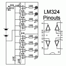
The circuit is conventionally designed with an eight LED audio level meter made from two low-power quad op-amps utilizing the LM324. Volume Unit. The eight LED audio level meter circuit serves as a visual representation of audio signal levels, providing...